Ka B/C overlap (Hughes) Thread

scopus

Specialist Contributor
Joined
Mar 25, 2005
Messages
3,194
Reaction score
3,832
Points
113
Age
59
My Satellite Setup
Primesat/Famaval 1.8 PF C/ku/Ka, Octagon SX8HD1, SX88, Openbox S3 Mini HD-V8S Freesat V7 HD-V8 Finder, Amiko A4K Combo, Satlook Colour HD Spectrum, Sansui A909 Amp and BOSE Acoustimass speakers for the audio.
My Location
Staffs UK
...........................................................................................................................................................................................................................................................................
... Oh behave, did it the other week .... it's absolute quality. It throws the dish and all it's added weight about like a rag doll, has absolutely no problem at all pulling it off the extreme end positions. Do you have any problems pulling off lol ??. The higher pulse count/deg is spot on and has given the ASC1 positioner a new lease of life
Yah, makes mince meat of pulling mine off!! Real quality piece of kit!.
 

John

Enthusiast.
Joined
Jan 1, 2000
Messages
3,770
Reaction score
5,596
Points
113
Location
North Nottinghamshire.
My Satellite Setup
Elite 2.2 PF - CM1.8 - CM1.2 - Gibertini 1.25.
Ku - Ka -C & Ext C.
PC cards-TM5402 receivers.
Promax FSM.
My Location
North Nottinghamshire.
... @Llew & @VS , can i run a couple of things past you for guidance please.
Iv'e done the resistor H/V switching mod on the Hughes this morning and as far as i can see iv'e not bricked it.
Using an unmodded one as reference, removed from OMT, so showing two open ports into room, the current draw on 12volts supply is 139mA, 17volts = 144mA .
Using the analyser shows a decent flat response across the band at about 63.4 dBuV and covering each port in turn to find the active one shows it to be on the RHC/V port only, no analyser response from the LHC/H port. Switching from 12v to 17 v makes no difference as to be expected.
-------------------------------
The modded one , using Llews resistor values of 22k & 1.2k :
Current draw @ 12v = 152mA & 17v = 161mA.
Using analyser as above, Now only LHC/H port active , nothing on RHC/V port and no change in port selection when switching from 12 to 17 volt supply change.
Gain response is slightly lower on the modded unit at 60dBuV across the band.

Your views gladly accepted.
 

Llew

cerca trova...
Staff member
Joined
Jan 1, 2000
Messages
16,236
Reaction score
4,205
Points
113
Age
81
My Satellite Setup
Triple Dragon, Dreambox 8000, Echostar AD3000ip, TBS6522,6925,6983 PCie cards.
Gibertini 1.25m motorised dish driven by the AD3000, with either Inverto BU Quad or Norsat / XMW Ka LNBs . SMW 1.05m + 3 other dishes. Speccy: Promax HD Ranger+
My Location
The Flatlands of East Anglia
Hi John, sorry, I've been busy repositioning the Gibby mast today. Anyhow, my current draw is considerably higher than yours, 13V @ 195mA and 18V @ 204mA.
The current difference between the two voltage states is the same as yours though, 6mA.

I'm going through a DiSEqC switch, later I'll check minus the switch when I've tidied up outside.
 

John

Enthusiast.
Joined
Jan 1, 2000
Messages
3,770
Reaction score
5,596
Points
113
Location
North Nottinghamshire.
My Satellite Setup
Elite 2.2 PF - CM1.8 - CM1.2 - Gibertini 1.25.
Ku - Ka -C & Ext C.
PC cards-TM5402 receivers.
Promax FSM.
My Location
North Nottinghamshire.
Hi John, sorry, I've been busy repositioning the Gibby mast today. Anyhow, my current draw is considerably higher than yours, 13V @ 195mA and 18V @ 204mA.
The current difference between the two voltage states is the same as yours though, 6mA.

I'm going through a DiSEqC switch, later I'll check minus the switch when I've tidied up outside.
......................................................................................................................................................................
Cheers llew, my Hughes is the same as Chris's (scopus) which we do believe has a slightly different pcb layout to yours and VS's. After speaking to Chris earlier i can confirm that his mod does exactly the same as mine. Was just wondering if it was just a resistor value tweek to activate the proper H/V switchover voltages ?.... dunno
 

Llew

cerca trova...
Staff member
Joined
Jan 1, 2000
Messages
16,236
Reaction score
4,205
Points
113
Age
81
My Satellite Setup
Triple Dragon, Dreambox 8000, Echostar AD3000ip, TBS6522,6925,6983 PCie cards.
Gibertini 1.25m motorised dish driven by the AD3000, with either Inverto BU Quad or Norsat / XMW Ka LNBs . SMW 1.05m + 3 other dishes. Speccy: Promax HD Ranger+
My Location
The Flatlands of East Anglia
Can you check the output of the voltage comparator where you've wired in the resistor divider?
Should change state when changing 13/18V.

May be a borderline change at the comparator input, not enough to switch states.

Could try VS's values, can't remember what they are at present, should be in this thread somewhere.
 

John

Enthusiast.
Joined
Jan 1, 2000
Messages
3,770
Reaction score
5,596
Points
113
Location
North Nottinghamshire.
My Satellite Setup
Elite 2.2 PF - CM1.8 - CM1.2 - Gibertini 1.25.
Ku - Ka -C & Ext C.
PC cards-TM5402 receivers.
Promax FSM.
My Location
North Nottinghamshire.
Can you check the output of the voltage comparator where you've wired in the resistor divider?
Should change state when changing 13/18V.

May be a borderline change at the comparator input, not enough to switch states.

Could try VS's values, can't remember what they are at present, should be in this thread somewhere.
..........................................................................................................................................................................

... Will do the comparator check first llew , cheers.
 

Vipersan

Emmett Browns Ghost
Joined
Jun 29, 2009
Messages
10,918
Reaction score
6,663
Points
113
Age
66
My Satellite Setup
IP9000HD +
TD110 Dish and TD88 Dish in Tandem
66°East to 60°West.
AZbox PrmHD + OpnbxS9HD + Skybox + DrHD F15
2x VboxII AZ-EL
2 m+ Alcoa PF + BSC421 C-Band lnbf...
+SS2/TwHnS2-3200 pci/TBS6925 pci
1.5 Fortec Star -Gbox - HtoH Ku/Ka/C
My Location
UK
It is important that you do that comparator switch check ..
Monitor the switched output voltage when changing the input voltages ie H/V ..
Llew is probably right regarding borderline switching voltages ...but a comparator is as a comparator does ...and this providing it is the same device ...tweaking those resistor values should yield results ..
Good luck John..
You'll sort it eventually ..

rgds
VS
 

John

Enthusiast.
Joined
Jan 1, 2000
Messages
3,770
Reaction score
5,596
Points
113
Location
North Nottinghamshire.
My Satellite Setup
Elite 2.2 PF - CM1.8 - CM1.2 - Gibertini 1.25.
Ku - Ka -C & Ext C.
PC cards-TM5402 receivers.
Promax FSM.
My Location
North Nottinghamshire.
..........................................................................................................................................................................

... Will do the comparator check first llew , cheers.
......................................................................................................................
Bare with me on this Llew, i'm not as clever as you & VS remember ..... On the 10393, on pin 1 out it reads 4.84volts and does not change when lnb supply voltage is changed.
Pin 3in voltage, once through the voltage divider is: 1.3v with 12volt lnb supply and 1.97v with 17v lnb supply.
 

Vipersan

Emmett Browns Ghost
Joined
Jun 29, 2009
Messages
10,918
Reaction score
6,663
Points
113
Age
66
My Satellite Setup
IP9000HD +
TD110 Dish and TD88 Dish in Tandem
66°East to 60°West.
AZbox PrmHD + OpnbxS9HD + Skybox + DrHD F15
2x VboxII AZ-EL
2 m+ Alcoa PF + BSC421 C-Band lnbf...
+SS2/TwHnS2-3200 pci/TBS6925 pci
1.5 Fortec Star -Gbox - HtoH Ku/Ka/C
My Location
UK
To make it easier to reference the info you need John ..
I've gathered all the relevant info ..on this mod here >>>


Yep ..it's a comparator ..
Here are the voltages per pin in the osc ON state
pin 1 = 5V
pin 2 = 0.75v
pin 3 = 1.35v
pin 4 = gnd
pin 5 = 0.75v
pin 6 = 1.36v
pin 7 = 0.24v
pin 8 = VCC (5v)


and again in the OSC OFF state

pin 1 = 0v
pin 2 = 0.75v
pin 3 = 0v
pin 4 = gnd
pin 5 = 0.75v
pin 6 = 0v
pin 7 = 4.8v
pin 8 = VCC (5v)

So in theory we only need isolate pins 3 and 6 and install 2 x potential dividers 4 resistors generating control from the lnb input voltage to control these pins to emulate switching of the Hughes ?
2 x 10k pots should suffice ?

I am of course assuming your rev X Hughes uses the same chip..?

...scratch the original idea as pins 3 and 6 both require 1.36v presumably they use the opposite inverting inputs only 0ne potential divider needed to drive both pins ?? looks like a simple toggle arrangement
On pins 3 & 6 = 1.35v and OFF pins 3 and 6 = 0v


......................................

Better and better ..
pins 3 and 6 are the + inv and - non inv inputs respectively and appear to be joined together and linked to a transistor ....so this should be easier ..
as only one track cut needed to isolate both comparator inputs ..
Is yours the same Llew ?
..........................................
.Now ..I cannot find any DC switched via the Diode having lifted the centre leg ,,,
So the 1.36v no longer appears at all ..thus ..I assume the Schotty simply provides a small DC voltage by half wave rectifying the 27mhz AC RF when present...presumably provide by a tune circuit or amplifier ..involving that Choke you mentioned Llew..
So we can ignore this ..remove the diode ..and simply apply our own 1.36v ...generated with a potential divider from the 13/18v line..
This all makes sense and is why the Hughes functions in VERTICAL mode when no 27mhz is present ..
ie zero volts on pins 3 and 6 of the comparator..
Time to give my old eyes a rest ..but were halfway home and hosed I think Llew ..
..................................................................

Ok ..so a very rough addition ..
pins 3 and 6 isolated from the rectified 27mhz signal..
15k up to lnb input ..and 1.2k to ground ..the mid point to pins 3 & 6 of the comparator ..has pins 1 and 7 toggling between 0v and 4.8v ..on alternate H and V looped scans from the TBS card.
NOW my eyes hurt ..
lol
Tomorrow I'll fit the divider properly with some ferrite beads added..
In fact I might increase the resistors by a factor of 10 ..150k/12k ...so as not to load/damp the output signal too much.
rgds
VS
....................................................................
 

scopus

Specialist Contributor
Joined
Mar 25, 2005
Messages
3,194
Reaction score
3,832
Points
113
Age
59
My Satellite Setup
Primesat/Famaval 1.8 PF C/ku/Ka, Octagon SX8HD1, SX88, Openbox S3 Mini HD-V8S Freesat V7 HD-V8 Finder, Amiko A4K Combo, Satlook Colour HD Spectrum, Sansui A909 Amp and BOSE Acoustimass speakers for the audio.
My Location
Staffs UK
Going to have to get mine back out now and have a play too.....
 

John

Enthusiast.
Joined
Jan 1, 2000
Messages
3,770
Reaction score
5,596
Points
113
Location
North Nottinghamshire.
My Satellite Setup
Elite 2.2 PF - CM1.8 - CM1.2 - Gibertini 1.25.
Ku - Ka -C & Ext C.
PC cards-TM5402 receivers.
Promax FSM.
My Location
North Nottinghamshire.
To make it easier to reference the info you need John ..
I've gathered all the relevant info ..on this mod here >>>


Yep ..it's a comparator ..
Here are the voltages per pin in the osc ON state
pin 1 = 5V
pin 2 = 0.75v
pin 3 = 1.35v
pin 4 = gnd
pin 5 = 0.75v
pin 6 = 1.36v
pin 7 = 0.24v
pin 8 = VCC (5v)


and again in the OSC OFF state

pin 1 = 0v
pin 2 = 0.75v
pin 3 = 0v
pin 4 = gnd
pin 5 = 0.75v
pin 6 = 0v
pin 7 = 4.8v
pin 8 = VCC (5v)

So in theory we only need isolate pins 3 and 6 and install 2 x potential dividers 4 resistors generating control from the lnb input voltage to control these pins to emulate switching of the Hughes ?
2 x 10k pots should suffice ?

I am of course assuming your rev X Hughes uses the same chip..?

...scratch the original idea as pins 3 and 6 both require 1.36v presumably they use the opposite inverting inputs only 0ne potential divider needed to drive both pins ?? looks like a simple toggle arrangement
On pins 3 & 6 = 1.35v and OFF pins 3 and 6 = 0v


......................................

Better and better ..
pins 3 and 6 are the + inv and - non inv inputs respectively and appear to be joined together and linked to a transistor ....so this should be easier ..
as only one track cut needed to isolate both comparator inputs ..
Is yours the same Llew ?
..........................................
.Now ..I cannot find any DC switched via the Diode having lifted the centre leg ,,,
So the 1.36v no longer appears at all ..thus ..I assume the Schotty simply provides a small DC voltage by half wave rectifying the 27mhz AC RF when present...presumably provide by a tune circuit or amplifier ..involving that Choke you mentioned Llew..
So we can ignore this ..remove the diode ..and simply apply our own 1.36v ...generated with a potential divider from the 13/18v line..
This all makes sense and is why the Hughes functions in VERTICAL mode when no 27mhz is present ..
ie zero volts on pins 3 and 6 of the comparator..
Time to give my old eyes a rest ..but were halfway home and hosed I think Llew ..
..................................................................

Ok ..so a very rough addition ..
pins 3 and 6 isolated from the rectified 27mhz signal..
15k up to lnb input ..and 1.2k to ground ..the mid point to pins 3 & 6 of the comparator ..has pins 1 and 7 toggling between 0v and 4.8v ..on alternate H and V looped scans from the TBS card.
NOW my eyes hurt ..
lol
Tomorrow I'll fit the divider properly with some ferrite beads added..
In fact I might increase the resistors by a factor of 10 ..150k/12k ...so as not to load/damp the output signal too much.
rgds
VS
....................................................................
...........................................................................................................................................................
... Wowser !, i await with baited breath Master.
 

John

Enthusiast.
Joined
Jan 1, 2000
Messages
3,770
Reaction score
5,596
Points
113
Location
North Nottinghamshire.
My Satellite Setup
Elite 2.2 PF - CM1.8 - CM1.2 - Gibertini 1.25.
Ku - Ka -C & Ext C.
PC cards-TM5402 receivers.
Promax FSM.
My Location
North Nottinghamshire.
Going to have to get mine back out now and have a play too.....
.....................................................................................................................................................

There's always somebody to lower the tone :D:D
 

scopus

Specialist Contributor
Joined
Mar 25, 2005
Messages
3,194
Reaction score
3,832
Points
113
Age
59
My Satellite Setup
Primesat/Famaval 1.8 PF C/ku/Ka, Octagon SX8HD1, SX88, Openbox S3 Mini HD-V8S Freesat V7 HD-V8 Finder, Amiko A4K Combo, Satlook Colour HD Spectrum, Sansui A909 Amp and BOSE Acoustimass speakers for the audio.
My Location
Staffs UK
.....................................................................................................................................................

There's always somebody to lower the tone :D:D
Hehe....I also await the results from the Master...
 

Llew

cerca trova...
Staff member
Joined
Jan 1, 2000
Messages
16,236
Reaction score
4,205
Points
113
Age
81
My Satellite Setup
Triple Dragon, Dreambox 8000, Echostar AD3000ip, TBS6522,6925,6983 PCie cards.
Gibertini 1.25m motorised dish driven by the AD3000, with either Inverto BU Quad or Norsat / XMW Ka LNBs . SMW 1.05m + 3 other dishes. Speccy: Promax HD Ranger+
My Location
The Flatlands of East Anglia
A similar reminder of my patch -

Hi Guys, I needed a slightly lower triggering voltage for the comparator, or it wouldn't switch reliably every time between V and H voltages. So I made my ratio 22K to 1.2K.

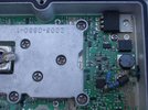
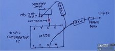
Pin 3 (input to one half of the dual comparator) and 6 (to the other half of the comparator) are, as we found, connected together, but as pin 6 is now isolated from the original 27MHz rectified voltage via the Schottky diode, only pin 3 and pin 2 (comparison voltage) are now being used.

Here's my mod, plus a sketch as the photo isn't too clear where connecting points are. I've taken my H/V LNB voltages directly from the LNB input with no problems - I think VS took his from the input to the regulator?


Hughes VH Mod.JPG

Hughes LNB Mod.JPG
 

Vipersan

Emmett Browns Ghost
Joined
Jun 29, 2009
Messages
10,918
Reaction score
6,663
Points
113
Age
66
My Satellite Setup
IP9000HD +
TD110 Dish and TD88 Dish in Tandem
66°East to 60°West.
AZbox PrmHD + OpnbxS9HD + Skybox + DrHD F15
2x VboxII AZ-EL
2 m+ Alcoa PF + BSC421 C-Band lnbf...
+SS2/TwHnS2-3200 pci/TBS6925 pci
1.5 Fortec Star -Gbox - HtoH Ku/Ka/C
My Location
UK
[QUOTE="- I think VS took his from the input to the regulator?


View attachment 95009

View attachment 95010[/QUOTE]

Indeed I did Llew ..which may explain our different choice of resistor values ...
but so long as the chosen values produce a working voltage in the correct region ..
It will work..
This was a joint effort on which Llew and Myself collaborated ...and got a repeatable result after many experiments and false starts.
rgds
VS
 

Llew

cerca trova...
Staff member
Joined
Jan 1, 2000
Messages
16,236
Reaction score
4,205
Points
113
Age
81
My Satellite Setup
Triple Dragon, Dreambox 8000, Echostar AD3000ip, TBS6522,6925,6983 PCie cards.
Gibertini 1.25m motorised dish driven by the AD3000, with either Inverto BU Quad or Norsat / XMW Ka LNBs . SMW 1.05m + 3 other dishes. Speccy: Promax HD Ranger+
My Location
The Flatlands of East Anglia
A (very) brief summary of our trials and tribulations getting this LNB to switch polarities (RHCP/LHCP).

After finding that in the US this Hughes 19.2-20.2 GHz LNB port switching is acheived using a 27MHz continuous waveform added to the LNB input over the cable connection, we set about developing a circuit that would accomplish this.

Not trivial. A voltage comparator (LM393N) wired to a 27MHz xtal oscillator circuit was constructed, with the oscillator switching on and off by changing the 14/18V condition to the comparator via the H/V switching from the receiver or Crazyscan. Several problems with this, as you needed the output from the receiver to power the LNB and receive the IF o/p, while also switching the 27MHz circuit. This made it difficult to supply a decent 27MHz waveform to the LNB; various types of filters were tried with no clear end result. Too much harmonic and other artefacts prevented successful switching at the LNB.

A look inside the LNB provided the answer - a 393 comparator! (actually the 10393 version). A 27MHz filter circuit provided the necessary voltage switching via a Schottky diode for the comparator to switch the o/p on or off, depending on presence or absence of 27MHz w/f at the filter. It's this comparator's inputs that we modified to use for the H/V switching from the receiver.

So - that's how we have arrived at making the circuit we're using now (with slight differences in component values).
 

John

Enthusiast.
Joined
Jan 1, 2000
Messages
3,770
Reaction score
5,596
Points
113
Location
North Nottinghamshire.
My Satellite Setup
Elite 2.2 PF - CM1.8 - CM1.2 - Gibertini 1.25.
Ku - Ka -C & Ext C.
PC cards-TM5402 receivers.
Promax FSM.
My Location
North Nottinghamshire.
A (very) brief summary of our trials and tribulations getting this LNB to switch polarities (RHCP/LHCP).

After finding that in the US this Hughes 19.2-20.2 GHz LNB port switching is acheived using a 27MHz continuous waveform added to the LNB input over the cable connection, we set about developing a circuit that would accomplish this.

Not trivial. A voltage comparator (LM393N) wired to a 27MHz xtal oscillator circuit was constructed, with the oscillator switching on and off by changing the 14/18V condition to the comparator via the H/V switching from the receiver or Crazyscan. Several problems with this, as you needed the output from the receiver to power the LNB and receive the IF o/p, while also switching the 27MHz circuit. This made it difficult to supply a decent 27MHz waveform to the LNB; various types of filters were tried with no clear end result. Too much harmonic and other artefacts prevented successful switching at the LNB.

A look inside the LNB provided the answer - a 393 comparator! (actually the 10393 version). A 27MHz filter circuit provided the necessary voltage switching via a Schottky diode for the comparator to switch the o/p on or off, depending on presence or absence of 27MHz w/f at the filter. It's this comparator's inputs that we modified to use for the H/V switching from the receiver.

So - that's how we have arrived at making the circuit we're using now (with slight differences in component values).
..............................................................................................................................................................................................................................................

And without your two's pioneering work on this and other stuff, i and a few others would be stumped. Greatly appreciated.
 

scopus

Specialist Contributor
Joined
Mar 25, 2005
Messages
3,194
Reaction score
3,832
Points
113
Age
59
My Satellite Setup
Primesat/Famaval 1.8 PF C/ku/Ka, Octagon SX8HD1, SX88, Openbox S3 Mini HD-V8S Freesat V7 HD-V8 Finder, Amiko A4K Combo, Satlook Colour HD Spectrum, Sansui A909 Amp and BOSE Acoustimass speakers for the audio.
My Location
Staffs UK
..............................................................................................................................................................................................................................................

And without your two's pioneering work on this and other stuff, i and a few others would be stumped. Greatly appreciated.
I'll second that!!
 

John

Enthusiast.
Joined
Jan 1, 2000
Messages
3,770
Reaction score
5,596
Points
113
Location
North Nottinghamshire.
My Satellite Setup
Elite 2.2 PF - CM1.8 - CM1.2 - Gibertini 1.25.
Ku - Ka -C & Ext C.
PC cards-TM5402 receivers.
Promax FSM.
My Location
North Nottinghamshire.
@ VS & @Llew .... via the voltage divider was you looking at getting around 0.6 volts on IC pin3 to make it toggle once you change the H/V lnb supply volts ?. After a bit of a play this morning i can make my unit switch ports at approx 0.57v for RHC port and approx 0.75v upwards for LHC port. When on a 17 volt or so lnb supply, i'm now trying to find the toggle volts required via the divider to toggle me onto other polarity after iv'e selected 12volt lnb supply...... seems a bit critical ?.
 

Vipersan

Emmett Browns Ghost
Joined
Jun 29, 2009
Messages
10,918
Reaction score
6,663
Points
113
Age
66
My Satellite Setup
IP9000HD +
TD110 Dish and TD88 Dish in Tandem
66°East to 60°West.
AZbox PrmHD + OpnbxS9HD + Skybox + DrHD F15
2x VboxII AZ-EL
2 m+ Alcoa PF + BSC421 C-Band lnbf...
+SS2/TwHnS2-3200 pci/TBS6925 pci
1.5 Fortec Star -Gbox - HtoH Ku/Ka/C
My Location
UK
It may well be John that you have ..yet another version of this lnb ..
that said ..it really doesn't matter what the required voltage required to switch actually is ...so long as it is sufficient to perform the switch action relative to the voltage on the other comparator input pins..
..whatever works for your unit is ok ..
The principle is more important than the actual voltage ..as this may depend on the version of lnb used ..
ie not set in stone.
rgds
VS
 
Last edited:
Top