New Lnb changer

I worked on my sg2100 clone. the recalculate command (E0 31 6F 00) causes a reset of the values stored in the motor and erases all our settings when I was hoping that it only resets the index of the pulse counter, about the pulses I have 12300 pulses for 160°.
the motor refuses commands exceeding + or - 80°. I did not define the limits but the motor stops well in stop.
Trust do you still have the functional limit stops?
 
Yes , one long cam detects the zero and easter part of the clarkbelt and the small cam is for the endswitch
 
You count twice as much pulses as I did .
Probably you count difup and difdown puls . My counter only difup
 
i just read eeprom 24c02 when motor is far east and far west .

est68b8
26808​
sud810a
33034​
west98fd
39165​
 
Today I finished the 360º Technirotor project .
Last week I made a 360º gear at my leathe .
With a flex I made from a Moteck SG2100 worm (equal pitch to Technirotor) a cuttingtool .
Separated the middle part of the original gear with a holesaw and machined it to fit in the chamber of the new wheel and secured it with screws .

360 gr wormwiel.webp360 gr wormwiel parts.webpmachining 360º wheel.webp360 ready.webp360 wheel bolted.webp

On the wormwheel a 180º rim for the east sector recognition and a small rim for the endswitch .
Go To Reference is working fine .

As I earlier mentioned , with the original motor there is no more than 270º movement possible using the east / west buttons in the motormenu .
Even with the button at the rotor , 270º is the limit .
Years ago I modded the small gearbox inside by taken away one reduction step ( ± 3.7 : 1 ) speeding it up and reducing the amount of pulses /º
With that motor total movement of 340º by using the east / west buttons in the motormenu .
340º movement in 31 sec / 18 V -- 42 sec / 13 V
Unfortunately , the accuracy by stopping is bad , overshooting the position , even at Vert. 13 V
Setting 46º in Usals makes a 170º movement .


fast.webp
 
The inaccuracy is with the gearbox modification as I understand it.

At 270° you still get 11 LNB's. I have taken the division 132-108-72-36-0-24-48-72-96-120-136 as an example, which can of course be adapted to individual needs.

Die Ungenauigkeit ist mit der Getriebemodifizierung, wie ich das verstanden habe.

Bei 270° kommt man aber immerhin schon auf 11 LNB's. Ich habe hier als Beispiel die Teilung 132-108-72-36-0-24-48-72-96-120-136 angenommen, die man natürlich individuellen Bedürfnissen anpassen kann.
 
The inaccuracy is with the gearbox modification as I understand it.

At 270° you still get 11 LNB's. I have taken the division 132-108-72-36-0-24-48-72-96-120-136 as an example, which can of course be adapted to individual needs.

Die Ungenauigkeit ist mit der Getriebemodifizierung, wie ich das verstanden habe.

Bei 270° kommt man aber immerhin schon auf 11 LNB's. Ich habe hier als Beispiel die Teilung 132-108-72-36-0-24-48-72-96-120-136 angenommen, die man natürlich individuellen Bedürfnissen anpassen kann.

No Femi , its caused by the increased speed , almost four times faster .
The motor runs a bit ahead after being switched off .
If that fast movement is wanted , maybe JP can program the positioner to slow down the motor just before stopping .
Just for the tests I diggid up that fast motor to get over that 270 dgr limit .
An other option if 340 dgr is really needed is changing the 11 t motorgear for a 13 or 14 t .
In that case the original pulses can be used .
 
The speed and accuracy of the TechniRotors is fine with me.

What I would also like is that the positions of the azimuth and elevation motors are always approached from one direction, which significantly minimizes play in the moving parts.

Example:
Eutelsat 16A has a value of 2000

if I always drive from "bottom" to "top", for the Astra 19.2E in position 2027, the engine would only have to start in 2023, for example, which is in one line anyway.
Different now at Eutelsat 7B, it is at position 1921. Now the motor should move first to 1917 and then to 1921.

I could imagine that a target position minus a certain value, here in the example minus four, is not a very big programming effort.


Die Geschwindigkeit und Genauigkeit der TechniRotors ist für mich in Ordnung.

Was ich mir noch wünschen würde, dass die Positionen der Azimuth- und Elevations-Motoren immer nur aus einer Richtung angefahren werden, was das Spiel in den beweglichen Teilen erheblich minimiert.

Beispiel:
Eutelsat 16A hat den Wert von 2000
wenn ich immer von "unten" nach "oben" fahre, müßte zum Astra 19.2E auf Position 2027 der Motor erst z.B. 2023 anfahren, was ohnehin in einer Linie liegt.
Anderes jetzt bei Eutelsat 7B, er liegt auf Position 1921. Jetzt sollte sich der Motor erst auf 1917 und dann auf 1921 bewegen.

Ich könnte mir vorstellen, dass eine Zielposition minus einen besteimmten Wert, hier im Beispiel minus vier, kein sehr großer Programmieraufwand ist.
 
I see what you mean, but it's a sign of a very important play in your mount!
I experienced this situation a few years ago on my set but I eliminated this problem by using more perfect axes and an overall counterweight for the mount.
I can by software make the engine do what you say but during the initial setting it will be very weird!
But i will think about it

Ich verstehe, was du meinst, aber es ist ein Zeichen für ein sehr wichtiges Spiel in deinem Reittier!
Ich habe diese Situation vor ein paar Jahren an meinem Set erlebt, aber ich habe dieses Problem beseitigt, indem ich perfektere Achsen und ein Gesamtgegengewicht für die Montierung verwendet habe.
Ich kann die Engine per Software dazu bringen, das zu tun, was Sie sagen, aber während der anfänglichen Einstellung wird es sehr seltsam sein!
aber ich werde darüber nachdenken
 
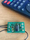
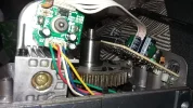
I installed a pulse divider board in my SG-2500A. It contains a CMOS divider IC 4040 and has a divider ratio of 4:1, i.e. the pulses counted by the Hall sensor are divided by four and only then transferred to the motor circuit board for evaluation. This means that you can give a Diseqc motor more travel without a lot of effort, provided the gear wheel has enough teeth. For testing, I approached and saved three positions with the JPC-Posi, all saved positions are approached cleanly, repeatedly and precisely, just great :D

Ps: The limit switch positions still have to be redone in order not to drive into the gear gap :)
IMG_0370.webpIMG_0371.webpIMG_0372.webpIMG_0373.webpIMG_0374.webpIMG_0375.webp
 
A bit late in, but from memory the Dark Motor devices I have here (based on the serial numbers they are from 2011), have no mechanical limit adjustments, the switches are locked into the casing at approximately 85 - 90 degrees from zero. The main cogs and gearbox components are all metal (with substantial bearings top and bottom) . The main wheel is toothed to approximately 270 degrees meaning removal of the limiting microswitches should provide a reasonable range for multi LNB work in the Trust endpoint design.

Though I've got other plans for my boom arm(s).

I will strip one down later to verify the above is correct.
 
A bit late in, but from memory the Dark Motor devices I have here (based on the serial numbers they are from 2011), have no mechanical limit adjustments, the switches are locked into the casing at approximately 85 - 90 degrees from zero. The main cogs and gearbox components are all metal (with substantial bearings top and bottom) . The main wheel is toothed to approximately 270 degrees meaning removal of the limiting microswitches should provide a reasonable range for multi LNB work in the Trust endpoint design.

Though I've got other plans for my boom arm(s).

I will strip one down later to verify the above is correct.
Ah, slightly different to how I remembered it.

Travel to each of the switches is fixed at 80 degrees, the main cog has a total sweep of around 240 degrees.

Next to take the switches out and see what happens.
 

Attachments

  • 1.webp
    1.webp
    217.3 KB · Views: 22
  • 2.webp
    2.webp
    127.2 KB · Views: 24
  • 4.webp
    4.webp
    249.9 KB · Views: 24
  • 5.webp
    5.webp
    544.4 KB · Views: 25
  • 6.webp
    6.webp
    463.6 KB · Views: 22
  • 3.webp
    3.webp
    185.1 KB · Views: 26
I installed a pulse divider board in my SG-2500A. It contains a CMOS divider IC 4040 and has a divider ratio of 4:1, i.e. the pulses counted by the Hall sensor are divided by four and only then transferred to the motor circuit board for evaluation. This means that you can give a Diseqc motor more travel without a lot of effort, provided the gear wheel has enough teeth. For testing, I approached and saved three positions with the JPC-Posi, all saved positions are approached cleanly, repeatedly and precisely, just great :D

Ps: The limit switch positions still have to be redone in order not to drive into the gear gap :)
View attachment 143808

try this :

div2.webp
 
Back
Top