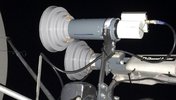
Titanium PLL C Band LNBs

s-band

Member
Joined
Feb 7, 2016
Messages
1,252
Reaction score
2,003
Points
113
My Satellite Setup
1.5m IRTE PF, Invacom SNF-031, TBS6983,
Various L, S, C, X & Ka bits. 1.2m S/X/Ku/Ka Prodelin on Az-El (being refurbished), 1.8m Precision PF with Bullseye Ku LNB or various C & X bits
My Location
Essex
Reference Harmonics
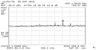
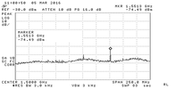
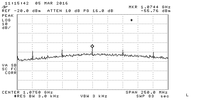
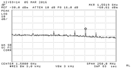
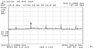
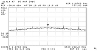
I have been looking at the performance of these as I (and others) noticed that they exhibit some strange behaviour. I hope to look at NF & polarisation (unless anyone else has?) but attached are some plots showing harmonics of the 25MHz reference present in the output. In addition to that, although I can’t nail it down, the noise output looks spikey at times. Some notes:
-The noise floor on the plots is a few dB higher than you would see on a dish as the LNBF was looking at absorber at room temperature.
-I tried absorber & shielding around the oscillator which had little effect.
-Probing the thing I could not find high levels of harmonics near the chip. Measurements were swamped by the output signal (inc its spurs)
-At these levels, the spurs might not have much effect on TV but would if they hit a narrow band signal.

Lite Version
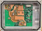
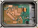
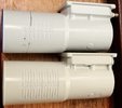
Because I chopped the scalar ring of my C1W-PLL, I bought a lite version, for its ring, thinking it would be a de-selected model of the same. However, the lite is different in some respects (see pics).
Other differences Lite vs non-lite:
-NE3503M04 vs. NE3512S02 front end
-something else vs. NE3503M04 2nd stage
-Different body casting
-Scalar rings deeper on Lite (and f/d calibrations different on body)
-Noise o/p ~10-20dB higher on lite (gain/NF not measured)
-25MHz spurs similar levels but different structure.
I'll try and do a comparison on-air some time.

One thing to note, as Osmocom point out, there are unused screw holes in the C1W-PLL which could allow water to get in. Probably not a problem for PF but for offset dishes water may run down the feed.

The titaniums are amazing value compared to my 1st LNBs from 20 years ago. I’ve spent long enough for now but may add more some time.


Links:
Search Results for Query: titanium c band | Satellite & Digital TV Support forums
Titanium Satellite - Sales / Design / Development / Distribution /Customer Support
C Band LNB Ext Ref Mod - Miscellaneous Projects - Osmocom - Open Source Mobile Communications
page
NE3503M04 | Renesas Electronics Europe
NE3512S02 | Renesas Electronics
12v_1075mhz.png 12v_1500mhz_lite.png 12v_1500mhz.png 18v_1075mhz.png 18v_1500mhz_lite.png 18v_1500mhz.png c1w_lite.jpg c1w_regular.jpg lite_vs_regular.jpg
 
Last edited:

s-band

Member
Joined
Feb 7, 2016
Messages
1,252
Reaction score
2,003
Points
113
My Satellite Setup
1.5m IRTE PF, Invacom SNF-031, TBS6983,
Various L, S, C, X & Ka bits. 1.2m S/X/Ku/Ka Prodelin on Az-El (being refurbished), 1.8m Precision PF with Bullseye Ku LNB or various C & X bits
My Location
Essex

Costactc

Regular Member
Joined
May 30, 2012
Messages
811
Reaction score
763
Points
93
Age
59
My Satellite Setup
3m channel master mesh-24" vonweise actuator-ps1 x2 lnbf(L)-pansat ap3500 positioner-x2 premium III-vu+solo2.
2.4m fortec solid-24" vonweise actuator-esx 241 lnbf(c)-vbox 7 positioner- dm800.
1.2m fortec-24"sj actuator-invacom snh-031--tm 5402 m3.
My Location
Canada
Both my C1 and C2 Titanium lnb have been collecting dust in my garage since their arrival. Regular dro lnb outperform them hands down.
 

scopus

Specialist Contributor
Joined
Mar 25, 2005
Messages
3,267
Reaction score
3,923
Points
113
Age
60
My Satellite Setup
Primesat/Famaval 1.8 PF C/ku/Ka, Octagon SX8HD1, SX88, Openbox S3 Mini HD-V8S Freesat V7 HD-V8 Finder, Amiko A4K Combo, Satlook Colour HD Spectrum, Sansui A909 Amp and BOSE Acoustimass speakers for the audio.
My Location
Staffs UK
Both my C1 and C2 Titanium lnb have been collecting dust in my garage since their arrival. Regular dro lnb outperform them hands down.
I totally agree, my old Astrotel Precision Gold gives far superior performance....
 

s-band

Member
Joined
Feb 7, 2016
Messages
1,252
Reaction score
2,003
Points
113
My Satellite Setup
1.5m IRTE PF, Invacom SNF-031, TBS6983,
Various L, S, C, X & Ka bits. 1.2m S/X/Ku/Ka Prodelin on Az-El (being refurbished), 1.8m Precision PF with Bullseye Ku LNB or various C & X bits
My Location
Essex
Scopus, costactc, interesting. I've compared the lite to the non-lite and convinced myself that the lite is up to 1dB better, varying over the band. I tried a not very scientific sky-ground noise figure measurement and got around 1.2dB for the C1W. I probably had some ground in my sky noise as I was not totally clear of trees.
I need to get a simple WR229 feed as my old co-rotor is too much of a lump to hang on the IRTE. I've got an old Chaparral (20K??) LNB and a 120K LNA (1983 vintage!) to try.
The idea of PLL LO is attractive for narrow band. I grafted one of these (Ebay 121096363971) into the Lite which seems to work ok after a bit of fiddling with the levels.
 

Costactc

Regular Member
Joined
May 30, 2012
Messages
811
Reaction score
763
Points
93
Age
59
My Satellite Setup
3m channel master mesh-24" vonweise actuator-ps1 x2 lnbf(L)-pansat ap3500 positioner-x2 premium III-vu+solo2.
2.4m fortec solid-24" vonweise actuator-esx 241 lnbf(c)-vbox 7 positioner- dm800.
1.2m fortec-24"sj actuator-invacom snh-031--tm 5402 m3.
My Location
Canada
I live in the c band haven of this world and every test that I have put these lnb to have come up with the same results. I presently have the psi x2 dro lnbf on my 3m CM mesh and bsc 422 lnbf on my 2.4m Fortec solid. My single and dual (C1 + C2) are not in use and probably never will be.
 

nelson_b

Contributor
Joined
Jul 27, 2008
Messages
1,985
Reaction score
2,075
Points
113
Age
74
My Satellite Setup
Strong 4375 driving a 2.4 m Channel Master dual focus offset + Invcom Quad C120 K/U l.n.b. + BSC 421 and Zinwell C band l.n.b.,s - DR HD F15 - TM5302 - Octagon SX88+Optima - GT Media V7 - HD receivers. + other dishes currently in use - Antique 3.0 m Prodelin P.F. - Channel Master 1.8 m offset - Channel Master. 1.2 m.
My Location
North West Yorkshire - near Lancashire & Cumbria borders.
hi - after getting of to quite a good start using this l.n.b.
over the longer term though i,m finding the results increasingly erratic . good at some polarity/frequencies and poor at others. ... and with no pattern to these odd results i cant really blame a "faulty" l.n.b ...
BSC 421 still giving me the best results on 1.8 c.m.offset and 3 m Prodelin p.f. ... out of ones i,v tried so far. :)
 

s-band

Member
Joined
Feb 7, 2016
Messages
1,252
Reaction score
2,003
Points
113
My Satellite Setup
1.5m IRTE PF, Invacom SNF-031, TBS6983,
Various L, S, C, X & Ka bits. 1.2m S/X/Ku/Ka Prodelin on Az-El (being refurbished), 1.8m Precision PF with Bullseye Ku LNB or various C & X bits
My Location
Essex
Nelson, I'm glad I'm not the only one who thinks they are erratic. The probes in the Tit feeds seem a bit short (and shorter in non-lite cf. lite). If I could reach, I'd try adding a bit to them.

While I'm at it: The scalar rings don't seem deep enough. They should really be >=1/4 wave. The C1W is 12.2mm, the Lite 18.3mm (1/4 wave at 4.1G) and the Chaparral 23mm

Has anyone any comments on the Norsat PLLs? (apart from them being expensive)
 
Last edited:

satkingdom

Regular Member
Joined
Feb 1, 2016
Messages
67
Reaction score
75
Points
18
Location
Turkey
My Satellite Setup
10 fixed offset antennas ranging from 107 cm to 170 cm with multifeed systems on them.
Next Machina3D Satellite Receiver
My Location
North-East of Turkey
hi - after getting of to quite a good start using this l.n.b.
over the longer term though i,m finding the results increasingly erratic . good at some polarity/frequencies and poor at others. ... and with no pattern to these odd results i cant really blame a "faulty" l.n.b ...
BSC 421 still giving me the best results on 1.8 c.m.offset and 3 m Prodelin p.f. ... out of ones i,v tried so far. :)
BSC 421 got better results on Sab120 ofset dish on Verticals but on Horizontals Titanium gave a slightly better performance. Overall, BSC 421 better on Asiasat7 (105,5 east).
 

s-band

Member
Joined
Feb 7, 2016
Messages
1,252
Reaction score
2,003
Points
113
My Satellite Setup
1.5m IRTE PF, Invacom SNF-031, TBS6983,
Various L, S, C, X & Ka bits. 1.2m S/X/Ku/Ka Prodelin on Az-El (being refurbished), 1.8m Precision PF with Bullseye Ku LNB or various C & X bits
My Location
Essex
Modifications to a C1W PLL Lite

Polarisation Switching

As received, the C1W Lite switched to H at 14.07V and back to V at 13.86V. Since the TBS6983 switches at 14.2V it will only switch polarisation if the cable is long enough to drop the voltage a bit. Adding a 2k7 resistor (circled red) moves the switching points to 14.6 and 14.3 which fixed the problem for me.

TCXO
I used one from an Ebay seller, Item 121096363971. There is no specification that I can find but it I guess it is 1-2ppm. It has the advantage that it has a trimmer built in so there’s no need to add anything. I used a Dremel to cut tracks on a bit of PCB to mount the TCXO. The PCB is grounded to the main board with some copper tape.

I removed 2 capacitors (yellow circles) and fed the 25MHz via thin co-ax as shown (magenta connection). It may not look like it but the coax is well clear of the filter on the main board. The TCXO o/p is capacitively coupled so there’s no need for an external capacitor. The drive to the IC is more critical than expected and there is a 510R resistor in series at the TCXO end. This forms a low pass filter with the coax capacitance and drops the level slightly. It’s a bodge but it works. The synthesiser gets very messy if the reference level is wrong so it is necessary to keep an eye on its spectrum. Unfortunately this could be hard if you don’t have any test gear.

The TCXO should run from 5V but I was too lazy to add another regulator so it is fed from the 6V line via a 120R resistor and decoupled with a 100n chip. It’s running from ~5.5V but seems ok.

c1w_lite_mods.jpg
 
Last edited:

s-band

Member
Joined
Feb 7, 2016
Messages
1,252
Reaction score
2,003
Points
113
My Satellite Setup
1.5m IRTE PF, Invacom SNF-031, TBS6983,
Various L, S, C, X & Ka bits. 1.2m S/X/Ku/Ka Prodelin on Az-El (being refurbished), 1.8m Precision PF with Bullseye Ku LNB or various C & X bits
My Location
Essex
Mods to C1W-PLL (not-Lite)

Polarisation
As received this switched at 15V to H and 14.5 to V. Curiously, there is an intermediate state when dropping from 14.7 to 14.6V. The level dropped by ~10dB before switching fully. That may be yet another reason why random changes in performance are seen. I didn’t investigate but maybe it’s when both front ends are on at the same time? It’s probably not needed but I changed the switching voltages to 15.9/15.2V by changing the circled resistor to 8k2 (was 10k)

TCXO
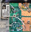
This was fitted in a different way, compared to the lite, on another piece of PCB with track hacked to suit. The PCB is grounded via a copper strap with some Kapton tape to prevent shorting to the main PCB tracks. As per Osmocom, the level is not really that critical. When doing the lite I hadn’t noticed that the duty cycle of the Rakon output changes dramatically if loaded resistively. That must have messed up the bias in the downconverter. For this one I put a 47p in series and then a 100p to ground to form a capacitive divider to drop the level. The supply was fed from the 6V line via a 220R decoupled with 100n. The voltage is still a bit high but it works.

The point marked “TP” can be used to probe with a counter without upsetting the TCXO.

Sealing
I also put some screws in the empty fixing holes and the holes for which I didn’t have short enough screws, I filled with sealant.

I don’t know why I spent so long on this but once I started….

C1W_Rakon_TCXO.jpg
 
Last edited:

Confucian

Regular Member
Joined
Mar 28, 2016
Messages
134
Reaction score
142
Points
43
Age
68
My Satellite Setup
1.4m Offset, 1.8m Prime Focus for C Band Aero
My Location
Dalystown, Ireland
Mods to C1W-PLL (not-Lite)
TCXO

This was fitted in a different way, compared to the lite, on another piece of PCB with track hacked to suit. The PCB is grounded via a copper strap with some Kapton tape to prevent shorting to the main PCB tracks. As per Osmocom, the level is not really that critical. When doing the lite I hadn’t noticed that the duty cycle of the Rakon output changes dramatically if loaded resistively. That must have messed up the bias in the downconverter. For this one I put a 47p in series and then a 100p to ground to form a capacitive divider to drop the level. The supply was fed from the 6V line via a 220R decoupled with 100n. The voltage is still a bit high but it works.

The point marked “TP” can be used to probe with a counter without upsetting the TCXO.

View attachment 92312

Hi, now for a silly question, can this mod be carried out without the need for specialist test equipment.?
 

satkingdom

Regular Member
Joined
Feb 1, 2016
Messages
67
Reaction score
75
Points
18
Location
Turkey
My Satellite Setup
10 fixed offset antennas ranging from 107 cm to 170 cm with multifeed systems on them.
Next Machina3D Satellite Receiver
My Location
North-East of Turkey
BSC 421 got better results on Sab120 ofset dish on Verticals but on Horizontals Titanium gave a slightly better performance. Overall, BSC 421 better on Asiasat7 (105,5 east).
I compared the two lnbs at Apstar-7 at 76.5° East and BSC 421 gave a better performance at 4111 H 4600 but what the most important thing was that when I turned the BSC 421 90 degrees and entered the frequency as 4111 V 4600 , I got almost one db. higher signal, which confirms my initial observation that its vertical performance is better. You can adjust the lnb to get the most important Transponders :)
 

s-band

Member
Joined
Feb 7, 2016
Messages
1,252
Reaction score
2,003
Points
113
My Satellite Setup
1.5m IRTE PF, Invacom SNF-031, TBS6983,
Various L, S, C, X & Ka bits. 1.2m S/X/Ku/Ka Prodelin on Az-El (being refurbished), 1.8m Precision PF with Bullseye Ku LNB or various C & X bits
My Location
Essex
You can adjust the lnb to get the most important Transponders :)
The same apples to the Titanium. It may be due to the LNAs but I have suspicions that some differences are cause by the difference in probe positions. For circular, optimal plate position can win up to a dB. Comparing the lite to normal, each has a frequency range that is better than the other.

can this mod be carried out without the need for specialist test equipment.?
Yes but ignore this bit:
The drive to the IC is more critical than expected and there is a 510R resistor in series at the TCXO end. This forms a low pass filter with ..........
As I found out later, the critical thing was the bias to the downconverter chip which must not allow the input voltage to go below 0V so follow this recipe:
When doing the lite I hadn’t noticed that the duty cycle of the Rakon output changes dramatically if loaded resistively. That must have messed up the bias in the downconverter. For this one I put a 47p in series and then a 100p to ground to form a capacitive divider to drop the level.

Setting the frequency without test gear will be a pain but if you set your SDR "ppm adjust" value correctly using an off-air reference, you could use the SDR to set the 25MHz TCXO by setting one of the harmonics that is present in the Titanium's IF output to an integral 25MHz.
 
Last edited:

John

Enthusiast.
Joined
Jan 1, 2000
Messages
3,894
Reaction score
5,903
Points
113
Location
North Nottinghamshire.
My Satellite Setup
Elite 2.2 PF - CM1.8 - CM1.2 - Gibertini 1.25.
Ku - Ka -C & Ext C.
PC cards-TM5402 receivers.
Promax FSM.
My Location
North Nottinghamshire.
Just a little input re: TiT,s .... totally poke and hope to pass a couple of hours but interesting results.
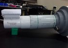
My Cband reception for circular until the other night consisted of a BSC 421 lnbf with a National ADL poloriser barrel. The BSC-421 died abruptly so i substituted it with one of my TiTs as a stop gap.
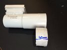
After reading the excellent posts above i decided to have a play, non scientific , just used my analyser to re-align onto 47.5 W afterwards. Using 47.5 West, SES Promo channel at 4.178 LHC the measured Quality reading on a TM 5502 was 52% absolute max on Vertical probe which -just- managed to get an unsteady lock , and 62% max on the Horizontal probe !. Didn't bother to get absolute dBuV readings off the analyser as i was only having a half hearted play. Decided to butcher one of my TiT's by taking off aprox 40mm off the length of the waveguide, re-united it with the poloriser barrel, set up a quick x-pol check and then re-did the comparison check again between the two probe voltage settings and the results were 59% on either probe with solid locks and no drop-outs. A quick look at the analyser across the whole band seems to look the same as original with no gain drop or increases that i can see. Might try and refine it at some point ??.
AVComm + Tit lnbf for circular pol...jpg TiT reduction..jpg
 

John

Enthusiast.
Joined
Jan 1, 2000
Messages
3,894
Reaction score
5,903
Points
113
Location
North Nottinghamshire.
My Satellite Setup
Elite 2.2 PF - CM1.8 - CM1.2 - Gibertini 1.25.
Ku - Ka -C & Ext C.
PC cards-TM5402 receivers.
Promax FSM.
My Location
North Nottinghamshire.
... Up to the hilt !!.
Shortened TiT lnbf..jpg
 

s-band

Member
Joined
Feb 7, 2016
Messages
1,252
Reaction score
2,003
Points
113
My Satellite Setup
1.5m IRTE PF, Invacom SNF-031, TBS6983,
Various L, S, C, X & Ka bits. 1.2m S/X/Ku/Ka Prodelin on Az-El (being refurbished), 1.8m Precision PF with Bullseye Ku LNB or various C & X bits
My Location
Essex
Modification to Cover Extended C-Band

Further butchery of the Titanium. I was curious to see if I could modify one to cover 4500-4800. The answer is a qualified "yes".

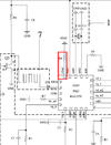
Grounding pin 20 of the RDA3570 switches the LO to 5750MHz. It is shown on the circuit for the patent as R8 (see attached) but I connected it direct to ground. I also bypassed the RF filter. There is a bit of a problem with the horizontal channel in that there seems to be a feedback loop from the output. Perhaps this is due to there being no rejection of IF in the LNA path. Adding a bit of absorber calmed it but there are still gain peaks. The overall gain is down about 10dB on the normal frequency range. It still works down to about 3.9GHz where the IF starts to cut off.

Testing it on the 1.5m IRTE PF I could just see a few TPs, none locked. I have posted scans: Satellites Community - 40.5°W SES-6 For comparison, qwer & Feedsat have scans there, made using real dishes. Taking into account the relative dish sizes, the LNB may not be too bad. I'm not sure it's working that well at 4800 though.

Edit: I modified the non-Lite, wide band version

rda3570_mod.png
 
Last edited:

John

Enthusiast.
Joined
Jan 1, 2000
Messages
3,894
Reaction score
5,903
Points
113
Location
North Nottinghamshire.
My Satellite Setup
Elite 2.2 PF - CM1.8 - CM1.2 - Gibertini 1.25.
Ku - Ka -C & Ext C.
PC cards-TM5402 receivers.
Promax FSM.
My Location
North Nottinghamshire.
Modification to Cover Extended C-Band

Further butchery of the Titanium. I was curious to see if I could modify one to cover 4500-4800. The answer is a qualified "yes".

Grounding pin 20 of the RDA3570 switches the LO to 5750MHz. It is shown on the circuit for the patent as R8 (see attached) but I connected it direct to ground. I also bypassed the RF filter. There is a bit of a problem with the horizontal channel in that there seems to be a feedback loop from the output. Perhaps this is due to there being no rejection of IF in the LNA path. Adding a bit of absorber calmed it but there are still gain peaks. The overall gain is down about 10dB on the normal frequency range. It still works down to about 3.9GHz where the IF starts to cut off.

Testing it on the 1.5m IRTE PF I could just see a few TPs, none locked. I have posted scans: Satellites Community - 40.5°W SES-6 For comparison, qwer & Feedsat have scans there, made using real dishes. Taking into account the relative dish sizes, the LNB may not be too bad. I'm not sure it's working that well at 4800 though.

Edit: I modified the non-Lite, wide band version

View attachment 94442
-----------------------------------------------------------------------------------------------------------------------------------------------------------------------------------------------------------------------------------------------------
Woah .... nice one indeed. I have a spare non-lite one so to speak, are the components & layout the same ?..... would love to make use of it for extended.
 

John

Enthusiast.
Joined
Jan 1, 2000
Messages
3,894
Reaction score
5,903
Points
113
Location
North Nottinghamshire.
My Satellite Setup
Elite 2.2 PF - CM1.8 - CM1.2 - Gibertini 1.25.
Ku - Ka -C & Ext C.
PC cards-TM5402 receivers.
Promax FSM.
My Location
North Nottinghamshire.
-----------------------------------------------------------------------------------------------------------------------------------------------------------------------------------------------------------------------------------------------------
Woah .... nice one indeed. I have a spare non-lite one so to speak, >>are the components & layout the same ?<<..... would love to make use of it for extended.

in all the excitement i mis-read your lnbf type .... i have the same type as you modded doh.
 

s-band

Member
Joined
Feb 7, 2016
Messages
1,252
Reaction score
2,003
Points
113
My Satellite Setup
1.5m IRTE PF, Invacom SNF-031, TBS6983,
Various L, S, C, X & Ka bits. 1.2m S/X/Ku/Ka Prodelin on Az-El (being refurbished), 1.8m Precision PF with Bullseye Ku LNB or various C & X bits
My Location
Essex
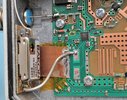
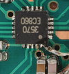
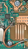
It is a C1W. Here are a couple of pics. If it looks a mess around the IC, that's because the connection is swimming in flux. If I were going to leave it like that I'd try to make a better connection. The 0.2mm wire looks like a bus bar, 0.1mm or less would be better. It is only grounded to the coax as that was the most convenient point - not ideal. The worst problem is the potential instability. You may need to move the absorber on the lid to keep it stable in horizontal pol. The instability and/or gain peaks can be seen above about 1700MHz in the IF. I added an extra screw (see top of ex_c-band.jpg) but I don't know if it made much difference.

To do it properly the LNAs need retuning, a filter needs to be between the LNA and mixer, the feed probes are probably wrong and the dielectric plate may be a bit too big. I guess that there's another couple dB to be had.

rda_mod.jpg ex_c-band.jpg
 
Last edited:
Top