s-band
Member
- Joined
- Feb 7, 2016
- Messages
- 1,276
- Reaction score
- 2,051
- Points
- 113
- My Satellite Setup
-
1.5m IRTE PF, Invacom SNF-031, TBS6983,
Various L, S, C, X & Ka bits. 1.2m S/X/Ku/Ka Prodelin on Az-El (being refurbished), 1.8m Precision PF with Bullseye Ku LNB or various C & X bits
- My Location
- Essex
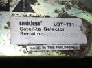
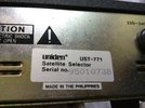
These excellent positioners are only 32 years old and still much better than non-professional modern ones. However, maybe age has caught up. For some time the positioner would go out of synch occasionally. Recently it would not move west and did not count pulse when moving east. It also refused to power up a couple of times.
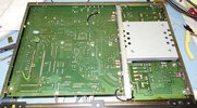
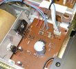
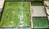
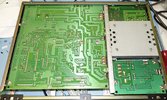
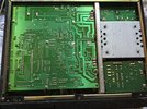
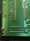
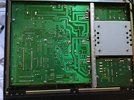
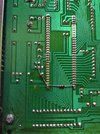
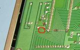
Checking voltages they did not quite make sense. The design relies on screws connecting the PCB ground areas to each other via the chassis. The screws had become loose. There is no direct ground connection between the PSU board and the main board except via the chassis.The ground area on the PCB to the top right is only connected to the rest of the board via the screw. That's the ground for the pulse input as well. If that screw doesn't make contact, the sensor ground isn't made. That may have been the cause of random mis-counts. The other ground failures must have caused loss of west movement. I'm surprised nothing blew up with the motor voltage possibly ending up where it shouldn't. Tightening the screws and adding the black wires fixed that problem. I checked a couple of spare 771s and both had loose screws.
The failure to switch on was due to the low voltage fuse holder falling apart. This was discovered when probing the voltages.
If you have one of these, I strongly recommend tightening all the ground screws, including those holding earth tags. I think it’s also a good idea to add direct connections between grounds as shown.

