VMA Stream Reader

New version: https://vma-broadcast.com/wp-content/uploads/2025/04/VMA Video Analyser Setup - 2026-02-23.zip

History:

2026-02-23
- VMA Transport Stream Analyser
- Improved HbbTV Analyser
- Links to Media URL's are detected and can be downloaded or streamed
to VMA Video Analyser or VMA Motion Analyser
- Fixed colour buttons
- Improved code injection

The built-in HbbTV Analyser, available in the Data tab, allows you to evaluate HbbTV services. It is not a full TV-grade HbbTV implementation, but rather a professional development and analysis tool.

By right-clicking inside the page, you can access WebView developer options that allow you to:

  • Save the complete page
  • Inspect HTML structure and JavaScript
  • Analyse network and media requests
This provides powerful insight for debugging, validation, and understanding HbbTV application behaviour.

New MEDIA Button​

The new MEDIA button detects all media links within the currently loaded HbbTV page and allows you to:

  • Download the selected media file
  • Stream it directly to VMA Video Analyser
  • Stream it directly to VMA Motion Analyser
Please note that media access may be subject to regional restrictions.
If you are outside the permitted region, the server may return HTTP 403 (Forbidden). In such cases, access may require a VPN service located within the permitted region.

1771841785519.webp
1771841902954.webp
1771841826948.webp
1771841879063.webp

1771843165241.webp
 
New version: https://vma-broadcast.com/wp-content/uploads/2025/04/VMA Video Analyser Setup - 2026-02-24.zip

History:

2026-02-24
-VMA Stream Reader
- Bug fix and optimization regarding startup and settings.cfg

IMPORTANT:

After installing this version please verify the default network adapter in Settings. The ordering has been changed and the Loopback Pseudo-Interface 1 - 127.0.0.1 is now always the first in the list. This makes it easier for NEW users, as the default settings.ini will use this adapter with IP 127.0.0.1. Before, the first recognized NIC was selected, which normally did not match the 127.0.0.1 IP. Having changed the order, any previously saved settings.ini will call the wrong NIC. Just go to Settings, select the correct NIC and press SAVE. From here on, all will work.
 

History​


2026-03-03​


VMA Transport Stream Analyser​

  • Added External Splitter option

VMA Stream Reader​


  • Added automatic launch of VMA Transport Stream Analyser using external TS Splitter
  • Added configurable cloned port for external TSA mode

VMA TS Splitter Pro​

  • Added command line options:
    • -input <ip> <port> – define UDP TS input source
    • -splitter <ip> <base> – per-service output starting at base port
    • -duplicate <ip> <port> – full TS duplication output
    • -mosaic – auto-start VMA Mosaic
    • -help – display usage information


What This Means​


You can now choose between two operating modes:


Normal Mode (existing behavior)​


VMA Stream Reader (Port 1)

VMA Transport Stream Analyser

Internal Splitter


New Optional External Splitter Mode​


VMA Stream Reader (Port 1)

VMA TS Splitter Pro (Port 2)

VMA Transport Stream Analyser
(internal splitter disabled)


Why This Matters​


With the splitter running as a separate optimized process:
  • Splitting becomes independent from TSA load
  • Mosaic no longer jitters if TSA is busy
  • Heavy analysis tasks (EPG parsing, Teletext decoding, data services, etc.) do not affect stream stability
  • The architecture becomes modular and more robust
This is particularly useful when running:
  • VMA Mosaic
  • EPG / Teletext intensive monitoring
  • High-service transponders
  • Long-term monitoring setups

1772541413668.webp

1772541483930.webp

Note: For external splitter to work when auto-starting VMA Transport Stream Analyser, you need to check "Use external TS Splitter" in VMA Transport Stream Analyser and press SAVE.
 
New version: https://vma-broadcast.com/wp-content/uploads/2025/04/VMA Video Analyser Setup - 2026-03-05.zip

History:

2026-03-05
- VMA Transport Stream Analyser
- External splitter is started from VMA Transport Stream Analyser
- When "Use External TS Splitter" option is set, VMA TS Splitter Pro is started
- VMA Transport Stream Analyser works with secondary port specified
- VMA Stream Reader
- Removed settings and logic to start external splitter

- VMA TS Splitter
- When started without arguments, will use default setting:
- Input: 127.0.0.1 1234
- Output: base port 20000
- No TS cloning
- Launch VMA Mosaic


This changes the use of the external splitter (VMA TS Splitter Pro). It is now directly controlled from inside VMA Transport Stream Analyser, where it makes sense: this way you can use the external splitter for any stream received via UDP.

I restored the settings in VMA Stream Reader, removing the option to start VMA Transport Stream Analyser in External Splitter mode - this is now configured inside VMA Transport Stream Analyser.

Finally, I restored the default setting for VMA TS Splitter Pro: when started without any argument (i.e. by double click) it uses the default input 127.0.0.1 1234, splits to base port 20000+ and starts VMA Mosaic.
 
Excuse me, but why do I need a mail program (!) to request a (demo) license? Other tools send it directly to the manufacturer via browser.
 
The software needs your Machine GUID, name, and email. At the moment, email is simply the most straightforward and transparent way for the software to pass that information to me, because you can clearly see what is being sent. I prefer this over hidden background communication.

That said, email is not strictly mandatory. If you prefer, you can send the same information manually by PM or by any other contact method I provide, and I can handle the request that way as well.
 
New version: https://vma-broadcast.com/wp-content/uploads/2025/04/VMA Video Analyser Setup - 2026-04-02.zip

2026-04-02
- VMA Steam Reader
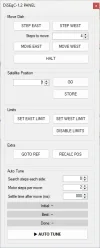
- Added DiSEqC-1.2 AUTO-TUNE to automatically fine tune the dish (requires a selected frequency)
- DiSEqC-1.2 form automatically pre-selects the correct memory position according to selected satellite
- Fixed PLS/MIS
- Several internal improvements

- VMA Transport Stream Analyser
- Improved Teletext module
- Several internal improvements

- VMA Motion Analyser
- Added new measurements
- Added User Guide

1775144299739.webp

1775144337176.webp
 
New version: https://vma-broadcast.com/wp-content/uploads/2025/04/VMA Video Analyser Setup - 2026-04-02a.zip

2026-04-02a
- VMA Steam Reader
- Improved DiSEqC-1.2 AUTO-TUNE
- Signal Analyser SNR bar now displays measured SNR and C/N margin (Δ) with colour-coded threshold

1775157806264.webp

1775157843647.webp

One of the small but meaningful changes in the 20260402a build is an upgrade to the SNR bar in the Signal Analyser panel. Here is what changed and why it matters.

The problem with raw SNR

Until now the SNR bar worked like every other signal meter — it filled up proportionally to the measured value and turned green above a certain percentage. This is fine for a quick sanity check but it is misleading in practice, because the SNR value that represents a healthy link is completely different depending on the modulation and FEC in use.

A DVB-S2 QPSK 1/4 transponder can operate error-free at −2.3 dB C/N. A 32APSK 9/10 transponder needs 16.8 dB C/N to do the same. If you show both on the same percentage scale, a 32APSK signal at 15 dB looks healthy (75% on the bar) when it is actually 1.8 dB below the demodulator's minimum operating point and shedding uncorrectable errors — while a QPSK 1/4 signal at 3 dB looks weak (15%) when it has 5.3 dB of rain fade margin in reserve.

This is a real source of confusion, particularly on contribution links and ACM transponders where the modulation changes dynamically.

What the new display shows

The SNR bar now shows two values simultaneously:

  • The measured SNR in dB — the absolute reading from the tuner, same as before
  • The C/N margin — the difference between the measured SNR and the minimum C/N threshold defined by ETSI for that specific modulation and FEC combination, prefixed with a Δ sign
Example: a transponder running DVB-S2 8PSK 5/6 has an ETSI-defined QEF threshold of 9.4 dB. If the tuner reports 15.5 dB SNR, the bar shows "15.5 dB Δ+6.1" — meaning there is 6.1 dB of headroom before errors enter the MPEG stream.

The label above the bar also updates to show the minimum threshold for the current modulation, for example "SNR (Min. 9.4 dB)", so the context is always visible.

Colour coding

The bar colour is derived from the margin, not from the raw SNR percentage:

  • Green — margin ≥ +3 dB. The link is robust and has real fade headroom.
  • Yellow — margin between 0 and +3 dB. The FEC is absorbing errors. Post-FEC BER will still read zero, but the link is fragile. A few dB of rain or dish misalignment would push it over the cliff.
  • Red — margin below 0 dB. The demodulator is below its minimum operating point. Uncorrectable errors are entering the MPEG stream. Immediate action required.
The critical insight here is the yellow zone. Without this display, a link operating 1 dB above threshold looks identical to one operating 10 dB above threshold — both show a clean BER of 0.00E+000. The margin display makes the difference visible before the link fails, not after.

Standards covered

The threshold table is derived from ETSI EN 302 307-1 (DVB-S2), EN 300 744 (DVB-T) and EN 300 429 (DVB-C), all using the QEF definition of BER = 10⁻⁷ after outer coding. Covered modulations are:

  • DVB-S: QPSK with all standard Viterbi rates
  • DVB-S2: QPSK, 8PSK, 16APSK and 32APSK with all LDPC rates
  • DVB-T: QPSK, 16QAM and 64QAM with all punctured convolutional rates
  • DVB-C: 16QAM through 256QAM
When the modulation is reported as Auto (common on ACM transponders), or when the standard is not in the table, the bar falls back to showing the raw SNR value with generic colouring — no misleading information is displayed.

Live update

The margin recalculates every timer tick using the live SNR reading and the last known modulation and FEC from the most recent blind scan result. On a fading satellite link you can watch the bar transition from green to yellow in real time as the signal degrades, well before the BER counter shows any activity — which is exactly the early warning a broadcast engineer needs to decide whether to call the uplink operator or wait for the fade to pass.
 
Last edited:
This finishes the update round of VMA Stream Reader targeted at DX usage: it is now much easier for a "power user" to scan (blind scan and direct tune mode), interpret (especial focus on the new SNR field that tells you if your dish is big enough) and analyze unknown/new signals (with the new IQ Analyser, ported from VMA Ultimate Stream Reader).

Combine this with VMA StreamReader CLI and you get total control over streamreader.dll and your tuner.

There is a trick: the TS INFO button only works with the reception is in LOCK = True state. If you have a weird transponder or if you used DIRECT TUNE, this field is either False or empty. In such case, double-click on the respective field and it will switch to True (but remain with a red background altering that this is a work around). You can now use the TS INFO button.
 
Back
Top