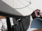
Restoring a working antique dish to full functionality..

yep just popped bagged a green chargeable one for myself...
sod the expense.
lol
 
No gurantees of course of the central accuracy of the laser pen...but imo...close enough for government work..

After 15 years of useless governments I can confidently state some twigs held together with cotton thread is more than good enough for government work . . .
 
Got the cat toy laser pen mounted where the lnb would fit...and unsurprisingly the laser pen does not produce a beam that is central.
Rotating the pen whilst switched on draws a circle with the laser point beam approximately 2 inches diameter which imo is just not good enough.
So..I decided to make one that mounts in the centre of the dish ..which will point toward the lnb holder....as per CHs suggestion.
The bore sighter will be fitted here when I receive it.
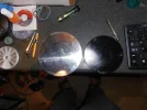
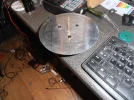
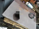
In the meantime I have removed the dish centre plate again ...and fabricated a 2mm thick aluminium disc to replace it.
you can see the original on the right (black)....with its replacement on the left.
Already centre drilled as are the screw mount points for fixing.
It is approx 2cm larger diameter ...why ?
Cos that was the diameter of the grass bowl I strarted with...
I ...can always reduce the diameter if I need to.
A work in progress so to speak.
 

Attachments

  • P1010047.webp
    P1010047.webp
    693.7 KB · Views: 106
Got the cat toy laser pen mounted where the lnb would fit...and unsurprisingly the laser pen does not produce a beam that is central.
Rotating the pen whilst switched on draws a circle with the laser point beam approximately 2 inches diameter which imo is just not good enough.
I would suspect you get the same if the pen is rotated on its own , indoors since the manufacturer isn't treating central placement of the laser as part of the design.
 
I would suspect you get the same if the pen is rotated on its own , indoors since the manufacturer isn't treating central placement of the laser as part of the design.
Totally agree Stephen...
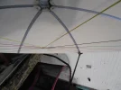
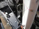
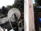
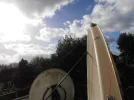
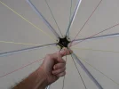
Anyhoo...for good or ill I have bolted a steel bracket to the mid point of the suspect panel ..and hooked a comealong to it and to the pole support metal which in turn is bolted to the wall of my house....
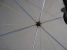
I added a click tighter every half hour....and although the steel bracket has deformed the folded over edge of the panel a little (hopefully can be corrected later with a hammer and the wooden former)...it does appear to have improved the overall shape and those green strings now touch the others and all colours appear to cross over at the same point.
I can only hope this improvement is retained once the steel cable is removed....but fwiw the winch will remain in place for a few days.
Your honest opinion of the attached pictures would be appreciated.
Is there method in my madness...?...time will tell.
but I cant see it being worse fwiw.
 

Attachments

  • P1010049.webp
    P1010049.webp
    214 KB · Views: 60
  • P1010050.webp
    P1010050.webp
    132.7 KB · Views: 44
  • P1010051.webp
    P1010051.webp
    333.7 KB · Views: 44
  • P1010052.webp
    P1010052.webp
    339.2 KB · Views: 39
  • P1010053.webp
    P1010053.webp
    278.5 KB · Views: 43
  • P1010054.webp
    P1010054.webp
    258 KB · Views: 45
  • P1010055.webp
    P1010055.webp
    403.6 KB · Views: 45
  • P1010056.webp
    P1010056.webp
    287.1 KB · Views: 61
Last edited:
Well, you can't get much better than that.

I would slacken off a turn or two and see if Christine goes back to her old shape, if so you can always re-tighten (and a bit more) to see if there is a point that allows the same profile once the cable is released.
 
Yes indeed...I had it in mind to tighten a couple of clicks past the current point of elasticity...
most likely I'll slacken the winch off tomorrow and take a look again at the strings.

Also interested to see if I can get ther bore sighter to project the green laser through that 14mm tunnel in the plastic cat toy holder postitioned at the lnb holder ...once I've made it of course...
....that _would_ indeed be quite an achievemet.

putting my eye to that tunnel I do see the string crossing point...but no way I can get a decent photo..
maybe after dark ?
 
Last edited:
OK, Ive carried out various post moves and copy overs from the Low symbol rate thread.

Will clean up other bits and bobs soon.
 
OK, Ive carried out various post moves and copy overs from the Low symbol rate thread.

Will clean up other bits and bobs soon.
Very much appreciated CH both by me and most likely other forum users.
 
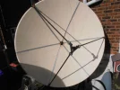
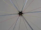
This mornings ping test...
Having left the dish overnight under tension after adding 2 more clicks to the winch.
I then released the winch tension....and checked all coloured strings were still touching at the centre.
They were as far as I could tell.
...but there is friction between the strings where they cross...sadly unavoidable...so I figured a ping test would answer some questions.
Hooking a finger under the whole bundle at the cross point and pulling forward a couple of inches...then release.#
Like plucking a guitar...then the release in theory would briefly remove the problem of friction and allow the strings to find their own resting place naturally.
These are the two pictures.
and in all honesty I dont think I'm going to get any closer..
max deviation can me measured in mm....

There will always be friction caused by the strings touching...but the fact that there is friction to me means none of the strings ride significatly higher or lower than others.

Maybe using a mono filament nylon fishing line might allow greater accuracy without much friction...but really...I think thats taking the this project to ridiculous extremes.
rgds
VS
 

Attachments

  • P1010009.webp
    P1010009.webp
    228.7 KB · Views: 37
  • P1010010.webp
    P1010010.webp
    181.3 KB · Views: 50
Last edited:
I think you could (once the boresight corrections are made) have the beginnings of a Ka compatible 1.8m reflector.

Well done !
 
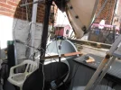
The selection of roller end plastics arrived this morning...one of which (and the reason I bought them) ...was a 60mm diameter centre marked already billet.
So armed with this I fitted it to the aluminium plate I made the other day with black self tapping screws.
see pix
obviously I can't proceed further until I have the bore sighter.
But I'm confident of central positioning...but as yet its diameter is an unknown.
A quick fitting test in the rain..
cest la vie
 

Attachments

  • P1010011.webp
    P1010011.webp
    654.9 KB · Views: 18
  • P1010012.webp
    P1010012.webp
    1 MB · Views: 18
  • P1010013.webp
    P1010013.webp
    138.2 KB · Views: 16
  • P1010014.webp
    P1010014.webp
    461.8 KB · Views: 21
Last edited:
Hi WS! I hope I am not too late, and your project is not finished yet. Nice job! On the very first page of this thread you said the C-band LNB has 60mm neck. I think the standart was 65mm, some older ones, of course could be less than 65mm. Other things I would do differently, instead of copper and aluminum hardware I would use INOX. Especially in case of the feedarms. But main principle, to which you are sticking is make things adjustable (if you can not make it perfect just do it adjustable), which is right. I have on the table the star-holder for 65mm LNB. In the middle of it there 65/40mm adapter, which is going to be cut in halve to hold 40mm LNB. It is also possible to make 65/25mm adapter as well. The ears of the star-holder need to be bent to needed angle before installing. Let me know if you are interested in this item. IMG_20261015_160654.webp
 
Hi WS! I hope I am not too late, and your project is not finished yet. Nice job! On the very first page of this thread you said the C-band LNB has 60mm neck. I think the standart was 65mm, some older ones, of course could be less than 65mm. Other things I would do differently, instead of copper and aluminum hardware I would use INOX. Especially in case of the feedarms. But main principle, to which you are sticking is make things adjustable (if you can not make it perfect just do it adjustable), which is right. I have on the table the star-holder for 65mm LNB. In the middle of it there 65/40mm adapter, which is going to be cut in halve to hold 40mm LNB. It is also possible to make 65/25mm adapter as well. The ears of the star-holder need to be bent to needed angle before installing. Let me know if you are interested in this item. View attachment 171086
I suspect you are correct about 65mm c band...
and yes that star holder is beautiful and if you were uk based Id take it off your hands ....it looks quite useful.
The original tripod support arms were made very dense ..very hard ....the surface feels like fibre glass and do not bend...but sadly I only have 2 now ...one got broken...many years ago when a roofer swung his ladders round.
If you drag your hand down its length you sometimes get what feels like fibreglass/resin needle like splinters.
here is a photo..
perhaps you can identify the material.
definately not metalic.
?

I am considering putting the 2 I have back on Christine ..and substituting just one with 15mm copper....
close enough diameter wise as the originals are 16mm.
 

Attachments

  • P1010015.webp
    P1010015.webp
    708 KB · Views: 21
Last edited:
Perhaps it is fiberglass. I was sending some stuff, including long feedarms to UK, before and after brexit. But, yes, shipping got more expencive.
 
Try a magnet to check if it has an internal metal skeleton

Glass fibre rods (from manufacturers of military field antennas) could be the source.
 
Try a magnet to check if it has an internal metal skeleton

Glass fibre rods (from manufacturers of military field antennas) could be the source.
Non magnetic CH...
Been taking a look here https://carbonfibreprofiles.com/products/grp-rods
for £30 I could replace all 3 IF they were a metre long.
Sadly not the case as they are 41.5 inches (105.41cm)
I cant order custom lengths so would have to go up a size to 2m which at almost £19 each (16.2mm) diameter is both wasteful and expensive.
I havent even looked into shipping costs.
If anyone has some glass fibre rods around 16mm diameter and longer than 106 cm you have a buyer waiting.
 
OK, VS, I see you want to go 16mm glass feedarms. Then take 3x1m, drill 5mm holes from at the ends and make internal M6 thread in those holes. Then take pieces of M6 threaded rods and fix them in the feedarms. On the attached picture I made a model to better understand the idea. If you get issues with the internal M6 thread, later you can enlarge the holes and thread M8 inside. IMG_20261016_165825.webp
 
Back
Top