Astra 2E & 2F: Sidelobes, Nulls and Spots

avionista

Regular Member
Joined
Nov 21, 2012
Messages
20
Reaction score
7
Points
3
My Satellite Setup
1.8m Famaval dish, Eaglebox 800 HD
My Location
Scotland & holiday home in S Costa Blanca
Any particular reason they would not use exactly the same shaped UK beam for 2E and 2F? I can't think of any as the satellites are built to same spec.

I can't think of any good reason to change 2E's antennas, which were already built and tested before 2F launched. Assuming 2F's footprints met the design specification - there is no evidence that this is not the case - there would be no good reason to change the antenna on 2E, unless the customer requested a change. This would not be cheap as a complete new antenna would have to be designed and tested, which would be costly for the customer and possibly compromise the programme timescale. I'll bet the Project Manager would resist this sort of late/unnecessary change so my money is on 2E's footprint being similar to 2F, with satellite position, aiming and manufacturing tolerances being responsible for any difference.
 

timo_w2s

Retired moderator
Joined
Sep 28, 2005
Messages
4,368
Reaction score
2,889
Points
113
My Satellite Setup
Vu+ Duo 4K SE
Dr.HD F15
My Location
Maidenhead, UK & Helsinki, Finland
Amazing technology.

Any particular reason they would not use exactly the same shaped UK beam for 2E and 2F? I can't think of any as the satellites are built to same spec.

Without wishing to sound too pedantic, they are not quite the same spec. They cover slightly different frequencies ranges and transponder setups and the European beam is slightly different if we can believe the footprints published on the SES site. Not to mention one satellite covers Africa and the other the Middle East. So there is room for differences, even if the UK reflector is the same on both.
 

Pride Of Cucamonga

Regular Member
Joined
Oct 20, 2013
Messages
293
Reaction score
113
Points
43
My Satellite Setup
Cheap piece of junk Spanish (Tecatel) 120cm(x110) dish, Inverto Ultra twin LNB and Sky HD box.
My Location
Valencia (city)
I can't think of any good reason to change 2E's antennas, which were already built and tested before 2F launched. Assuming 2F's footprints met the design specification - there is no evidence that this is not the case - there would be no good reason to change the antenna on 2E, unless the customer requested a change. This would not be cheap as a complete new antenna would have to be designed and tested, which would be costly for the customer and possibly compromise the programme timescale. I'll bet the Project Manager would resist this sort of late/unnecessary change so my money is on 2E's footprint being similar to 2F, with satellite position, aiming and manufacturing tolerances being responsible for any difference.

Yes and I believe 2E,F,G were ordered as a package so would be inefficient to design and manufacture three separate antennas. Also, 2E was originally intended to launch before 2F, so unlikely could be changed based on 2F reception reports. i guess 2G could potentially be modified, but seems little point as 2F is very good at restricting footprint to UK.
 

gambit

Member
Joined
Oct 14, 2008
Messages
18
Reaction score
17
Points
3
Location
Lancashire
My Satellite Setup
60cm fixed 28E
My Location
UK
The first null of 2f passes just east of Hamburg. Rostock is already in the sidelobe.

The beam shaping on 2E/2F uses antenna surface shaping to manipulate the footprint shape. Comparing the contours of the null points derived from the model of a simpler, non-shaped, 2.6m dish with the null points on the actual 2F UK spot footprint, the effect of the shaping produces a tighter beam. The contour for the first null actually crosses the NE coast of Spain well south of Barcelona - the reported null point. Similarly, the same contour crosses the N German coast almost on the Polish border, whereas, as cazhh reported, Rostock is actually in the sidelobe and the first null is between Hamburg and Rostock, further to the west.

The above is not surprising given that one reason for the beam shaping is a tighter beam. With a non-shaped dish you need a larger dish for a more sharply focused beam. The 2F UK shaped dish has resulted in a 1st null line equivalent to a larger, 3m diameter, non-shaped dish (at least for that 1st null line south and east of the UK).

The shaped dish can perhaps be thought of as a number of mini-dishes within the surface of the dish. It appears that, for regions south of the main lobe, the net effect is that of a plain dish whose curvature corresponds to a 3m diameter. This is, of course, pure speculation. However, a 3m plain, parobolic dish has the 1st null running straight through Barcelona, the second null passes just south of Gibraltar and the Costa del Sol and, at the midpoint of those two contours, the peak on the sidelobe passes through Valencia. Also, on the German coast, the first null is correct - between Hamburg and Rostock.

This reasoning would be more compelling if the Canaries, where 2F reception is possible, were sitting on the 2nd peak of the 3m dish. Sadly not so! To place the Canaries on that peak you have to assume a 2.6m dish. Is it possible that well away from the the main, central lobe, as in the case of the Canaries, the shaped dish behaves more like a plain paraboloid? However, you can't have it both ways. For me, that's one speculation too far. An alternative explanation for the Canaries is that, for some reason, the UK spot beam shaping has produced a Canaries hot spot, as is the case on the pan-European beam. But why would they do that?

It seems the only sane conclusion is that, if you want to model the whole footprint of a shaped dish, use the software used by the designers - but you may be able to model individual null contours using software intended for smooth, parabolic reflectors and playing with the dish diameter setting.

It is possible to obtain limited and student editions of modelling software for beam shaping. Examples: Grasp9, Cobr, Satsoft

See Section 15 of:

http://cdn.intechopen.com/pdfs/9287/InTech-Modern_communication_satellite_antenna_technology.pdf

 

Waveguide

Member
Joined
Jan 1, 2011
Messages
140
Reaction score
204
Points
43
My Satellite Setup
Dish and box
My Location
North
If you check the video (in reply #19 in this thread) all the antenna parts are clearly visible.
The big reflectors are there but also secondary reflectors and feed-horns. All of these parts
have "sidelobes" on their own (unwanted but unavoidable energy spillage).

Put these parts on a truck-sized irregular reflecting surface and try to calculate the position
of the sidelobes and nulls 36000 kilometers away.

Well, you have to calculate all reflections and diffractions (like ray-tracing) and then integrate
amplitude and phase of all the rays to get the total antenna far field pattern. That would be
close to impossible and also probably unnecessary. The shape of "the truck" is not well defined
if it consists of glued on heat reflectors and metal-coated kapton foil.

I've never bought a satellite but most antenna specifications set a fixed upper limit on sidelobe
levels and thats it. Where they happen to be or where the nulls are is not an issue.
(Unless you buy antennas with steerable nulls to avoid jamming but then you are wearing a
uniform have large budget to match.)

As a summary - unsymmetrical antennas with a truck-sized reflector on one side and dark
space on the other will not follow any simple design rules.

On the other hand it's fairly easy to measure the antenna patterns of an assembled satellite
in an anechoic chamber. You can make lots of amplitude/phase measurements over a 2D
surface and calculate the antenna far field pattern. It's not cheap though, large test chambers
are expensive.
 

gambit

Member
Joined
Oct 14, 2008
Messages
18
Reaction score
17
Points
3
Location
Lancashire
My Satellite Setup
60cm fixed 28E
My Location
UK
. . . The big reflectors are there but also secondary reflectors and feed-horns. All of these parts have "sidelobes" on their own . . . you have to calculate all reflections and diffractions (like ray-tracing) and then integrate amplitude and phase of all the rays to get the total antenna far field pattern.

Yes, I know. Calculating a diffraction pattern that includes spurious reflections is complex. That's why it is so surprising that the highly simplified model of a single, smooth, parabolic reflector seems to predict the shape of the 1st null from SW Spain all the way to NE Germany. Of course, maybe the prediction isn't really all that good. A proper test would need to check against more than just two points along the null contour and reliable reception reports would be needed for each of those "null" points.
 

davidcmadrid

Member
Joined
Sep 21, 2012
Messages
218
Reaction score
48
Points
28
Age
48
My Satellite Setup
40cm offset 19e, 1.5m 28e 1.2 M motor vu+
My Location
Madrid Spain
Astra 2 E/F/G has reflectors of diameter 2.6 meters. Interestingly despite the differing footprints all are the same diameter.
 

Huevos

Satellite Freak
Joined
Sep 11, 2008
Messages
6,038
Reaction score
1,277
Points
113
My Satellite Setup
57E to 58W, C-band and Ku, DVB-S2, 4:2:2 and blindscan.
My Location
38.5ºN, 0.5ºW
A proper test would need to check against more than just two points along the null contour
Well Analoguesat's 2F map disproves most of this thread. Perfect null contours would only occur on a non-shaped beam. On a shaped beam there are hot spots and cold spots. Barcelona is a cold spot, but the line doesn't continue as in the contour map someone posted.
 

Huevos

Satellite Freak
Joined
Sep 11, 2008
Messages
6,038
Reaction score
1,277
Points
113
My Satellite Setup
57E to 58W, C-band and Ku, DVB-S2, 4:2:2 and blindscan.
My Location
38.5ºN, 0.5ºW
As frequency gets higher the null moves further north. This can be seen on the spectrum output. I'm north of the southern Spain null and the higher frequencies in band C aren't as strong as the lower frequencies. This is as opposed to 1N part of the band where power levels are all pretty much uniform. (Transponders marked new are also 2F).

horizontal.jpg
 

cazhh

Regular Member
Joined
Oct 12, 2012
Messages
218
Reaction score
182
Points
43
My Satellite Setup
Laminas 180cm, Invacom Quad with Gib Feedhorn, 28.2 + 19.2, dreambox & tbs5922
My Location
Elmshorn, Schleswig-Holstein
There are pretty consistent reports from north jutland, the hamburg area, the braunschweig area, down to east of munich which suggest that there is a huge null line. And reports i've heard from the south of france fit into this assumption as well.
The issue with most maps is that people don't add at which time they've done their measurements. The signal level in the "border" area which is about 100km wide isn't constant. It varies up to 6SNR db every day. So if someone measures at noon and someone else does the same in the evening you will get completely different results which invalidates all maps i've seen so far.
There is a beam map on another site which you've probably seen. http://robssatellitetv.webs.com/rob astra 2f special beam uk 90 - 56.JPG
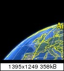
Although it looks weird i'm convinced that it is legit. The projection of the map is the same that you get when you look from the position of the satellite to the earth. I've done the excercize to use google earth and add the fieldlines on top of it:

It's the only position and viewangle which matches the reports at least from the eastern side of the beam.
 

davidcmadrid

Member
Joined
Sep 21, 2012
Messages
218
Reaction score
48
Points
28
Age
48
My Satellite Setup
40cm offset 19e, 1.5m 28e 1.2 M motor vu+
My Location
Madrid Spain
Huevos, i dont fully understand what your saying , in the sense you relate field intensity to TP / freq but it appears the signals are coming from three different satellites in your posted chart .. Could the differences not be from the differing charecteristic of transmitter as opposed to frequency ?
 
S

Steve Steve

Guest
There are pretty consistent reports from north jutland, the hamburg area, the braunschweig area, down to east of munich which suggest that there is a huge null line. And reports i've heard from the south of france fit into this assumption as well.
The issue with most maps is that people don't add at which time they've done their measurements. The signal level in the "border" area which is about 100km wide isn't constant. It varies up to 6SNR db every day. So if someone measures at noon and someone else does the same in the evening you will get completely different results which invalidates all maps i've seen so far.
There is a beam map on another site which you've probably seen. http://robssatellitetv.webs.com/rob astra 2f special beam uk 90 - 56.JPG
Although it looks weird i'm convinced that it is legit. The projection of the map is the same that you get when you look from the position of the satellite to the earth. I've done the excercize to use google earth and add the fieldlines on top of it:

It's the only position and viewangle which matches the reports at least from the eastern side of the beam.

Great Post Cazhh....at last a posting we all can understand ...in plain English ..with no special technical confusing terms of explanation .....nice one....!!
 

Huevos

Satellite Freak
Joined
Sep 11, 2008
Messages
6,038
Reaction score
1,277
Points
113
My Satellite Setup
57E to 58W, C-band and Ku, DVB-S2, 4:2:2 and blindscan.
My Location
38.5ºN, 0.5ºW
Huevos, i dont fully understand what your saying , in the sense you relate field intensity to TP / freq but it appears the signals are coming from three different satellites in your posted chart .. Could the differences not be from the differing charecteristic of transmitter as opposed to frequency ?
2 satellites. If you look at the spectrum transponders marked "2f" and "new" are all on 2f. As the frequency increases the power level is lower. That is because the null is further north as the frequency is higher (due to the aerial having more gain/directivity at higher frequencies).
 

Pride Of Cucamonga

Regular Member
Joined
Oct 20, 2013
Messages
293
Reaction score
113
Points
43
My Satellite Setup
Cheap piece of junk Spanish (Tecatel) 120cm(x110) dish, Inverto Ultra twin LNB and Sky HD box.
My Location
Valencia (city)
There are pretty consistent reports from north jutland, the hamburg area, the braunschweig area, down to east of munich which suggest that there is a huge null line. And reports i've heard from the south of france fit into this assumption as well.
The issue with most maps is that people don't add at which time they've done their measurements. The signal level in the "border" area which is about 100km wide isn't constant. It varies up to 6SNR db every day. So if someone measures at noon and someone else does the same in the evening you will get completely different results which invalidates all maps i've seen so far.
There is a beam map on another site which you've probably seen. http://robssatellitetv.webs.com/rob astra 2f special beam uk 90 - 56.JPG
Although it looks weird i'm convinced that it is legit. The projection of the map is the same that you get when you look from the position of the satellite to the earth. I've done the excercize to use google earth and add the fieldlines on top of it:

It's the only position and viewangle which matches the reports at least from the eastern side of the beam.

Interesting that footprint focal point is centre of England and not the centre of the target area (i.e. uk/ireland - which would be around Isle of Man). Guess because Scots/Irish have larger dishes installed. Anyway, Valencia is almost directly south of the focal point, which prob to do with unusual strength here.

EDIT And i guess Channel Islands only has 45cm dishes?
 

Huevos

Satellite Freak
Joined
Sep 11, 2008
Messages
6,038
Reaction score
1,277
Points
113
My Satellite Setup
57E to 58W, C-band and Ku, DVB-S2, 4:2:2 and blindscan.
My Location
38.5ºN, 0.5ºW

Pride Of Cucamonga

Regular Member
Joined
Oct 20, 2013
Messages
293
Reaction score
113
Points
43
My Satellite Setup
Cheap piece of junk Spanish (Tecatel) 120cm(x110) dish, Inverto Ultra twin LNB and Sky HD box.
My Location
Valencia (city)
Based on the map Cazhh posted - not at all scientific! Makes sense when thinking about where the larger dishes are.
 
Top