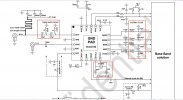
The AGC signal is taken from the connection between pin 5 of the RDA5815M and SI2166D pin 1.
The signal is a PWM filtered by a 4.7K resistor and a capacitor. The amplitude after the resistor is between 0V and 2V.
The useful part is between 1.4v (50%) and 2v (100%), the interface stage adapts the impedance then amplifies the voltage variation between 1.4v and 2V (threshold at 1.45v gain between 5 and 10).
At the output the signal varies between 0V and 3.5V, this signal, through a resistor, activates the galvanometer.
The same signal is sent to the positioner or an A/D converter (TLC548) gives the information to the microprocessor and makes it possible to adjust the position where the signal is maximum.
The program takes several steps forward and backward comparing the AGC power to find the best result and returns the dish to that point.
youtube:
the starting value is 2212, the program tests the AGC from 2212 to 2220 then 2212 to 2204, the best result is found at 2214