Advice Needed Vbox 3 and actuator wiring

AtOM13

Member
Joined
Feb 27, 2024
Messages
39
Reaction score
16
Points
8
Age
40
Location
near Marseille
My Satellite Setup
Triax 100cm, lnb Inverto black Ultra
CM120cm Laminas 150cm
My Location
Marseille
Hi guys,

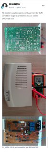
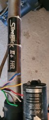
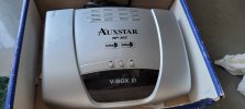
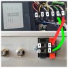
Following yours advices, I just found a "DiseQC Box" (vbox III ) for my CM 1.2m and his actuator.

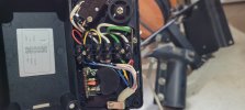
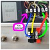
A Small bit of the wire is still attached to the actuator, but the cable seems very thin and looks like internet cable with 9 wires !
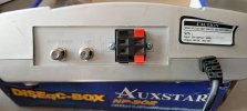
Inside actuator waterproof box, there's only 6 entries for wiring and on the vbox only 2 black and 2 red entries for the wires.

Don't want to damage it with bad wiring, so yours advices are welcome !
 

Attachments

  • 20240516_135110.jpg
    20240516_135110.jpg
    1.6 MB · Views: 104
  • 20240519_114100.jpg
    20240519_114100.jpg
    1.7 MB · Views: 57
  • 20240518_182526.jpg
    20240518_182526.jpg
    1.8 MB · Views: 45
  • 20240518_183623.jpg
    20240518_183623.jpg
    1.6 MB · Views: 61

Channel Hopper

Suffering fools, so you don't have to.
Staff member
Joined
Jan 1, 2000
Messages
35,781
Reaction score
8,649
Points
113
Age
60
Website
www.sat-elite.uk
My Satellite Setup
A little less analogue, and a lot more crap.
My Location
UK
Just treble up the two actuator wires, leaving one twisted pair for the reed switch sensor and you should be OK.
 

suedschwede

Member
Joined
Aug 5, 2018
Messages
174
Reaction score
259
Points
63
Age
58
My Satellite Setup
2.7m Laminas+Polarmount+JPC-Posi+SF8008
My Location
DE
A Vbox with +5V is required for the actuator because there is an electronic switching signal and no reed sensor is installed.
Either install a +5V tap into the Vbox or use an external +5V power supply.
 

AtOM13

Member
Joined
Feb 27, 2024
Messages
39
Reaction score
16
Points
8
Age
40
Location
near Marseille
My Satellite Setup
Triax 100cm, lnb Inverto black Ultra
CM120cm Laminas 150cm
My Location
Marseille
Ok thanks! so for wiring the motor is it like this picture (1 on 7 and 2 on 8) ?
But don't know where plug the 2 "sensors" from the Vbox (9 and 10) ?
Maybe they are provide +5v ?
 

Attachments

  • 20240520_101626.jpg
    20240520_101626.jpg
    840.1 KB · Views: 62

AtOM13

Member
Joined
Feb 27, 2024
Messages
39
Reaction score
16
Points
8
Age
40
Location
near Marseille
My Satellite Setup
Triax 100cm, lnb Inverto black Ultra
CM120cm Laminas 150cm
My Location
Marseille
So I made some tests today, actuator move fine :)
@suedschwede I put an external +5v like you said, but asking myself if I can plug with the Sensor 1 wire which provide 10v ???
 

Attachments

  • 20240520_101626.jpg
    20240520_101626.jpg
    865.8 KB · Views: 40
Last edited:

Terryl

Specialist Contributor
Joined
Apr 14, 2011
Messages
3,430
Reaction score
2,024
Points
113
Age
82
My Satellite Setup
OpenBox X5 on a 1 meter motorized dish.
And now a 10 foot "C" band dish.

Custom built PC
My Location
Deep in the Boonies in the central Sierra Nevada mountains of California.
No..If you use 10 volts instead of the 5 volts the unit requires, it may not work too long, if it says +5 V, you use +5V DC.

Running a circuit at double the required voltage may cause some serious damage, so that may not be repairable.
 

Channel Hopper

Suffering fools, so you don't have to.
Staff member
Joined
Jan 1, 2000
Messages
35,781
Reaction score
8,649
Points
113
Age
60
Website
www.sat-elite.uk
My Satellite Setup
A little less analogue, and a lot more crap.
My Location
UK
So I made some tests today, actuator move fine :)
@suedschwede I put an external +5v like you said, but asking myself if I can plug with the Sensor 1 wire which provide 10v ???
How would you know 10V is on the contact ?
 

a33

Specialised Contributor
Joined
Sep 24, 2009
Messages
1,282
Reaction score
743
Points
113
Age
64
My Satellite Setup
XSAT410
Rebox RE-9000
My Location
The Netherlands
Some V-boxes have an L7805 where you could take the 5 volt from.
But be carefull, there are several models V-boxes!

Some links:
post #38: v-box II manual
post #15: Generic Positioner 60 Slots

All at your own risk...

Greetz,
A33
 

ArloG

Member
Joined
May 18, 2023
Messages
35
Reaction score
28
Points
18
Age
54
My Satellite Setup
12' Fiberglass Dish, C2W & Geosat Pro lnbf, Titanium ASC-1, Osmio4k, Zgemma H7 Client
My Location
N. Central PA, USA
I'd like to help.
The v-box sensor input is designed to work with reed switch equipped actuators.
A switch enclosed in glass that operates when the round actuator magnet N-S poles get close enough to operate it.
Think of the wall switch in your home that you could operate with a magnet instead of your finger.
Except when you move the magnet away, the lights go off.

If the actuator has 3 terminals for the sensor wiring. Then a hall effect switch or an optical interrupter is used.
If it's a hall switch then the same type of magnet that operates a reed switch is used.
If an optical switch is used. There will be a slotted wheel that blocks or unblocks the sensor beam.

A reed switch will work just like shorting two wires together.
A hall or optical switch does the same. But needs an external power source to run the circuit.
When powered with a DC voltage. Normally 5 VDC. The sensor (pulse) connection and common (ground) will act just like the reed sensor wires will be shorted when the magnet operates it.

The v-box sensor terminals should have ~ 5 VDC if measured with a multimeter.
So the power supply operating the sensor in the actuator should be close to the same.
That is why on IRD receivers with motor controls and 3 wire sensor inputs, and/or polorotor skew control, have a +5 VDC terminal.
To power them if equipped.

Ground (common) should be connected to the outer braided shield.
+ 5VDC connected to one of the sensor wires. Preferrably the red wire so you don't forget.
And the sensor wire whatever color is left.
Inside, feed 5 VDC from a wall wart from the junk drawer. Make sure that you check the snipped wire polarity.
Send +5 VDC up the cable to the actuator (red wire).
Use the braided shield as the ground of the wall wart -5 VDC.
Connect the shield (braid) to the v-box black terminal.
And then the sensor wire from the actuator to the red v-box terminal.
Keep the sensor wires as far away from the actuator motor wires as you are able to.
Because the actuator motor can make some pretty dirty electrical noise that can cause false triggering that adds extra 'counts' to the v-box.

BTW. I've made several encoders for linear actuators. Hall effect switches with Schmitt triggers, optical encoders and slotted trigger wheels.
By far the best and most accurate are optical encoders. Especially when making a high resolution encoder.
I have a 12' dish with 36" actuator. And have increased the pulse counts from the stock 6 ppr of the actuator output shaft to 20.
It gives very accurate dish positioning and excellent repeatability.

Hope this helps a bit. I'm new here.
 

AtOM13

Member
Joined
Feb 27, 2024
Messages
39
Reaction score
16
Points
8
Age
40
Location
near Marseille
My Satellite Setup
Triax 100cm, lnb Inverto black Ultra
CM120cm Laminas 150cm
My Location
Marseille
@RimaNTSS :Y

Why do I have to shunt R3 resistance ?
 

Attachments

  • Screenshot_20240524_091659_Opera.jpg
    Screenshot_20240524_091659_Opera.jpg
    1.8 MB · Views: 39

AtOM13

Member
Joined
Feb 27, 2024
Messages
39
Reaction score
16
Points
8
Age
40
Location
near Marseille
My Satellite Setup
Triax 100cm, lnb Inverto black Ultra
CM120cm Laminas 150cm
My Location
Marseille
All is ok with this mod, no need to shunt R3 in my case, just take 5v from JP3 and ground
 

Attachments

  • branchement_5v_VBOX.jpg
    branchement_5v_VBOX.jpg
    377.4 KB · Views: 29
Last edited:

a33

Specialised Contributor
Joined
Sep 24, 2009
Messages
1,282
Reaction score
743
Points
113
Age
64
My Satellite Setup
XSAT410
Rebox RE-9000
My Location
The Netherlands
Would the schematics at the end of this thread indeed be the same as in this circuit board?

If yes, could somebody explain why, with a reed relais/relay, this R3 would be needed?

I would assume, that shunting R3 would put one terminal for the sensor at 0 Volt, but using the 0 Volt as an extra lead (blue in this case) from the circuit board is just as effective.
@AtOM13 : Am I correct that you use the red and blue wire now for the +5V and Ground, and only one terminal of the sensor terminals of your Vbox?

I'd like to understand, for further reference....

Greetz,
A33
 

ArloG

Member
Joined
May 18, 2023
Messages
35
Reaction score
28
Points
18
Age
54
My Satellite Setup
12' Fiberglass Dish, C2W & Geosat Pro lnbf, Titanium ASC-1, Osmio4k, Zgemma H7 Client
My Location
N. Central PA, USA
Here. Eliminate the confusion and hacking the v-box circuitry.
The hall, optical, and reed switches simply supply a switch closure.
The hall and optical switches need typically 5 VDC to operate.
I'm not sure why R3 would need shunted. As it was mentioned probing the pc board and finding 5 volts to tap off and plus 5 volts ground should be good enough. Unless shunting R3 would indeed provide a solid ground. I guess.

Everyone has a junk drawer full of wall wart USB 4.5 - 5 volt cell chargers.
And the thing about using one is they are short circuit proof.
The attached diagram solves cracking the v-box open and soldering jumpers to supply pixies to the actuator encoder.
 

Attachments

  • V-Box Hall PS.jpg
    V-Box Hall PS.jpg
    1.2 MB · Views: 28

AtOM13

Member
Joined
Feb 27, 2024
Messages
39
Reaction score
16
Points
8
Age
40
Location
near Marseille
My Satellite Setup
Triax 100cm, lnb Inverto black Ultra
CM120cm Laminas 150cm
My Location
Marseille
@a33 yes absolutely
@ArloG I try your method, it's works fine too

I think about another method by picking 10v from 'Sensor 1" vbox's output, directly in the actuator box using a resistor, to avoid 1 more 20 meters wire
 
Last edited:

ArloG

Member
Joined
May 18, 2023
Messages
35
Reaction score
28
Points
18
Age
54
My Satellite Setup
12' Fiberglass Dish, C2W & Geosat Pro lnbf, Titanium ASC-1, Osmio4k, Zgemma H7 Client
My Location
N. Central PA, USA
@a33 yes absolutely
@ArloG I try your method, it's works fine too

I think about another method by picking 10v from 'Sensor 1" vbox's output, directly in the actuator box using a resistor, to avoid 1 more 20 meters wire

Not really a good idea but you could try it. I'm guessing that if it was workable, it would have already been done.
And if you think about it. The hall sensor needs it's own Vcc to operate. Using a common power source would 'drag' it down when activated.
Believe me. And others. And think why a power tap into the v-box was necessary in the first place. The sensor needs it's own dedicated power rail.
Period.
You are free to see if you can wire in a reed switch in place of the hall unit. And use only 2 wires.
But still 2 wires out to the actuator invites motor noise. You need that shield. Shield and 2 wires or shield and 3 wires. It's how it's done. And has been. For like....ever.
For me. I use an ASC-1 actuator control. It also is meant for reed switches. There were add-on relays that allowed usage with hall/optical encoders.
But. Still. At least 3 wires are needed out to the sensor.
I made my own with a miniature Crydom SSR.
The hall sensor gets 5 volts from the terminal strip. Normally used to power a polorotor if one is used.
The hall sends back 5 volts through the SSR and lights the internal optocoupler.
The SSR output acts as a switch closure and triggers the ASC-1 internal optocoupler.
Hey man. It ain't my first day in industrial sensor interfacing and positional control.

Actually now thinking about it. In an attempt to get a nice square wave trigger into the ASC-1. And to extinguish it's own internal opto LED a bit quicker. I added a series resistor from the SSR out to the sensor in terminals. Worked slick! Nice, fast, and pretty square pulses.
And at 20ppr of the slotted optical encoder disc I made. Very high count resolution with a 36" actuator that tracks from 127W out to at least 40.5W.
 

Attachments

  • ASC1 Hall SSR.jpg
    ASC1 Hall SSR.jpg
    716.8 KB · Views: 24
Last edited by a moderator:

AtOM13

Member
Joined
Feb 27, 2024
Messages
39
Reaction score
16
Points
8
Age
40
Location
near Marseille
My Satellite Setup
Triax 100cm, lnb Inverto black Ultra
CM120cm Laminas 150cm
My Location
Marseille
Wow impressive job ! Dish actuators is a new world for me , so for the moment I just want a reliable and "simple" installation possible .
 

a33

Specialised Contributor
Joined
Sep 24, 2009
Messages
1,282
Reaction score
743
Points
113
Age
64
My Satellite Setup
XSAT410
Rebox RE-9000
My Location
The Netherlands
I would assume, that shunting R3 would put one terminal for the sensor at 0 Volt, but using the 0 Volt as an extra lead (blue in this case) from the circuit board is just as effective.

I guess the assumption is right. I discovered this 5V modification description:

Greetz,
A33
 

a33

Specialised Contributor
Joined
Sep 24, 2009
Messages
1,282
Reaction score
743
Points
113
Age
64
My Satellite Setup
XSAT410
Rebox RE-9000
My Location
The Netherlands
So, if I understand this V-Box modification correctly:
- there is already an opto-coupler in the V-Box (see the posi14 or posi15 schematics);
- you add an opto-coupler to your actuator.

This seems a bit funny, and unnecessary?
Can't you use just the opto-coupler in the actuator, and bypass the opto-coupler in the V-Box?

I just want to understand, but have no practical experience with V-Boxes whatsoever.....
So maybe there might be important reasons, to have two opto-couplers in series?

Greetz,
A33
 

ArloG

Member
Joined
May 18, 2023
Messages
35
Reaction score
28
Points
18
Age
54
My Satellite Setup
12' Fiberglass Dish, C2W & Geosat Pro lnbf, Titanium ASC-1, Osmio4k, Zgemma H7 Client
My Location
N. Central PA, USA
The reasoning is that the Crydom is self contained with Schmitt trigger and zero crossing switching.
Probably not told was I used a RC parallel network on the output of the SSR with a 'scope to look at the square wave pules and changed values. Actually used a pot wired as a voltage divider to determine the final resistor value.
Initially the output pulses weren't flat topped. The actuator encoder would trigger the SSR and the output spiked.
So cleaning it up for consistent, nice, clean square waves worked out nice.
Mind you. My slotted optical encoder wheel provides many more pulses than the standard 6 pole magnet that is standard in actuators.
Folks like Von Weise and Venture do allow you to configure an actuator for high res. encoders. But I believe 6 ppr of the output shaft is the norm.

And because of the higher resolution encoder. I found that there were miscounts. Usually when 'bumping' the actuator to get the best signal during initial signal finding and storing positions.
My ASC1 turns the counter off as soon as the H bridge relays are released. So any motor coast would 'skip a beat'.
It accumulated over time. That's why it's important to establish at least one satellite as the 0 counter sat.
I only found that out when I got a bit more experienced.
Before. When sync. got off a bit. I would go-to my favorite sat. Then unbolt the motor from the tube and vice grip the actuator shaft to peak signal again. Then slap the motor back on. I was like 'duh' after learning how resync worked.

I guess one other reasoning of using a stand alone SSR with opto is that it allows you to control your own voltage out to the actuator over cable.
Noise, impedance, reactance. The internal opto depends of its own voltage and current and getting that out to the actuator and back at a low voltage. If you can raise the voltage to a sufficient level to overcome any introduced noise and shape the output for nice, clean, pretty square waves. I think you know the answer to that.
Did you ever touch the tip of an RCA interconnect that is in a receiver phono input jack?
And do the same with an aux, tape, CD input?
What was the hum level?
Yeah!
 
Top