Advice Needed Vbox 3 and actuator wiring

a33

Specialised Contributor
Joined
Sep 24, 2009
Messages
1,332
Reaction score
759
Points
113
Age
64
My Satellite Setup
XSAT410
Rebox RE-9000
My Location
The Netherlands
The reasoning is that the Crydom is self contained with Schmitt trigger and zero crossing switching.
So it looks like you are referring to your own modification, not the one that was in the post that I linked.

I guess a schmitt trigger could indeed help with miss-counts? Otherwise an Solid State Relay would be a rather 'heavy' solution for just a pulses circuit, I would think; an opto-coupler (for low amperage) would be enough?

I guess one other reasoning of using a stand alone SSR with opto is that it allows you to control your own voltage out to the actuator over cable.
Noise, impedance, reactance. The internal opto depends of its own voltage and current and getting that out to the actuator and back at a low voltage.
I don't see that it would allow extra voltage control. With just one opto-coupler, you still need the 5V and ground for the diode (two terminals), and the pulse (and ground) (one extra terminal) for the pulse. The Pulse-circuit in the V-box then can be at any voltage you like.

But you are saying that having the pulse/ground-circuit in the V-box itself, is much better than having it over the Pulse/ground circuit over the (long) cable? Thus maybe reducing the effect of induced impulses over the cable a bit?

Has somebody ever tried, with just one opto-coupler?

Greetz,
A33
 

ArloG

Member
Joined
May 18, 2023
Messages
64
Reaction score
43
Points
18
Age
54
My Satellite Setup
12' Fiberglass Dish, C2W & Geosat Pro lnbf, Titanium ASC-1, Osmio4k, Zgemma H7 Client
My Location
N. Central PA, USA
So it looks like you are referring to your own modification, not the one that was in the post that I linked.

"Just tack in a few wires here and there". A sketch of the actual circuit mod and what actually is attained would settle me a bit.
Not even actually sure if every incantation of vbox has the same pc board layout. Something hinted at the end of the post that got lost in translation of "borking" the box.

Circuit mods abound. Thing is. You're 'robbing' (in the case of tapping into the VCC) a supply voltage that may be related to a stable circuit. No decoupling capacitors, etc. to assure no pulse noise backfeeds into the previous section. And there's the risk that accidentally shorting something could take out the circuit you tapped into.
But to be honest mine is not a modification. More like a very safe enhancement. Kill your vbox and a vbox you will be searching. Kill an SSR. Pfft. Probably not going to happen. And all signal conditioning needed to get a stable and repeatable pulse back to the snesor input will never cook the motor controller. Flat out the truth.


I guess a schmitt trigger could indeed help with miss-counts? Otherwise an Solid State Relay would be a rather 'heavy' solution for just a pulses circuit, I would think; an opto-coupler (for low amperage) would be enough?

A fellow in the USA going by the name magicstatic actually made and sold a submini relay board that interfaced with the ASC1 and vbox. Pretty much the same as my idea but with hard contacts. To interface reed switch only inputs to use with hall and opto equipped actuators.
Actually there is little to doubt if given a choice of using linear vs Schmitt trigger input/outputs. Or comparator interfaces. Perhaps even the good old 555.
SSR's come in all sizes and flavors. The Crydom I use is quite small (smaller than a pack of matches). 3-32 VDC input and can handle up to 10 VDC on the output. I have literally a pile of old interface boards from a machine that are populated with 6 SSR's each. The factory techs swapped them out some years ago because there were flimsy circuit breakers that once reset a few times. Would not reset anymore. So they came in and did the upgrade and simply threw the old ones in a box destined for the bin. I 'intercepted' them. Lol.


I don't see that it would allow extra voltage control. With just one opto-coupler, you still need the 5V and ground for the diode (two terminals), and the pulse (and ground) (one extra terminal) for the pulse. The Pulse-circuit in the V-box then can be at any voltage you like.

Within the limitations of the opto used (in the vbox) referring to the absolute maximums from the datasheet. Don't forget that. I measure 4.2 VDC at the dish. At the ASC1 5V terminal it's a solid 5V. Under load of a closed optical encoder at my actuator the voltage drops to around 3.7V (from memory).
FYI. The opto circuit in the vbox and ASC1 are practically the same.
You might take in account that every hall/optical encoder may not be the same. NPN/PNP output. Soruce/Sink. I have several old actuators in the pile here from seveaal manufacturers. Most with reed encoders. +P-. +S- terminals on the others. You would think that the minus and P terminals would provide contact closure and the plus and minus powers the sensor. You would think!


But you are saying that having the pulse/ground-circuit in the V-box itself, is much better than having it over the Pulse/ground circuit over the (long) cable? Thus maybe reducing the effect of induced impulses over the cable a bit?

Ahh. The old water/electricity analogy. Here she comes!. What happens if you hook 3 long garden hoses together with a spray nozzle at the end under city water pressure?
Open the nozzle and you get a good stream. For a few seconds. Then it kind of peters out.
What if you could raise the pressure at your hose bib at the house and put a regulator on it?
It takes time for the sensor switch to close. And what if a reed switch gets old or the magnet gets weak and the contacts bounce?
That LED in an opto extinguishes as current drops. Kind of like lowering an open hand over your eyes. At some point the light will be blocked and your brain will tell you it's dark.
Well. If you can extinguish and light the LED in the vbox at a fast and predictable rate (Schmitt trigger) instead of a signal propagating over a cable at low and unregulated current/voltage. Wouldn't that seem better?

I know for a fact that a small ku dish has a tight beamwidth. Fine.
I've put a 'sidecar' ku lnbf on my 12' dish. It''s a Geosatpro. For a fact it uses only a 3' circle of the entire dish.
And there is a wide swing in the arc where the dish moves where signal is locked and lost.
Heck. I was even getting overlapping signals from adjacent satellites 2 degrees separation. Then I found out what the 'ignore satellites X degrees' in the E2 menu was for.
Compared to c band. Where just a few 'clicks' of the counter (with the original 6 ppr magnet/reed switch) would cause drastic signal gain/loss.
The thing is comparable to a pair of binoculars and a nice telescope.
I wanted to increase the actuator resolution. With only the help of hall effect modules from Amazon at first. And then thru beam optical switches and fabricated slotted encoders. By far the best ever way.
With the hall setup and motor on my bench with an oscilloscoe to tune the sensor/magnet distance. I was still forever tweaking it on the dish.
Then, while watching the geartrain during an actuator retract with dish weight on it. I noticed that the gears did not stop immediately when the ASC1 turned it off.
So I remembered my industrial machine days and dug out a relay to fashion into a dynamic brake.
Motor off. Contacts close and through a 1 ohm power resistor, the armature is shorted dead. The motor and gears stop immediately now.
Actuator is powered. The contacts open and voltage is fed to the motor. Easy!

Sorry for the 'book'. I kinda' like this stuff.


Has somebody ever tried, with just one opto-coupler?
Haha. Has anyone ever drank just one beer?

Greetz,
A33
 
Last edited:

a33

Specialised Contributor
Joined
Sep 24, 2009
Messages
1,332
Reaction score
759
Points
113
Age
64
My Satellite Setup
XSAT410
Rebox RE-9000
My Location
The Netherlands
I guess a schmitt trigger could indeed help with miss-counts? Otherwise an Solid State Relay would be a rather 'heavy' solution for just a pulses circuit, I would think; an opto-coupler (for low amperage) would be enough?

I checked the HT48RXX datasheet, which is the base of the V-Box posi15 schematics (indicated/linked by me somewhere above).
e.g. here: HT48Rxx datasheet
Reading that, I found it also mentions Schmitt triggers for the I/O ports.
So I interpret that as there might already be a schmitt trigger active on the input port?

In that case, adding another schmitt trigger in the circuit would not at all be necessary, I would think.
But I am not really knowledgeable about these ICs and datasheets, I must confess. So it's just my lay-man everday's knowledge, that comes to that (preliminary) conclusion.

Am I overlooking something?

Greetz,
A33
 

ArloG

Member
Joined
May 18, 2023
Messages
64
Reaction score
43
Points
18
Age
54
My Satellite Setup
12' Fiberglass Dish, C2W & Geosat Pro lnbf, Titanium ASC-1, Osmio4k, Zgemma H7 Client
My Location
N. Central PA, USA
I believe it would be better to initiate the threshold trigger and send the pulse down the cable rather than using a linear detector at the trigger wheel. There really is no disadvantage of using a Schmitt device.
I did not snap a 'scope screenshot of the output of the interrupter wheel over around 75' of 2 conductor with shield. The shield used as common, or ground in the circuit.
To get in the geekery of it all. And hope it makes sense.

1) The sensor I have is probably the same that Rima just ordered. 3.3-5 VDC operating voltage.

2) The ASC1 provides +5 VDC to power a polorotor servo. And so I used that to power the sensor.

3) The SSR input states 3-32 VDC input capability. And that voltage lights its own LED inside.
When the sensor is blocked, It provided the pulse down the cable.

4) 5 volts at the SSR input triggers the output to conduct. There's your reed switch closure.

5) The 'scope waveform, with 5 volts (appx.) vertical excursion gave a bit of a top (trailing edge) slight overshoot at the end of the duration.
Adding a trimmer pot in series with the sensor input of the SSR. And adjusting the resistance to lower the waveform voltage a touch above the trigger threshold of 3 volts of the SSR. It's off threshold being (from memory)....2.3 volts? Very nice square wave with just a slight spike on the trailing edge. A box-o-parts of capacitors showed that adding a (again, have to look) 0.01 uf ?? across the input for a snubber.
Almost a perfect square wave pulse. And the output looked sweet.
The pot was read for resistance and a closest value resistor was chosen.

Now. The SSR worked just fine on its own with just the sensor connected to it. I just wanted to look at the waveform. Identified and cleaned the pulse up. That's what geeks do!

I know Magic Static make an interface that used an actual relay. Hard contact relays have their uses. SSR's don't suffer low current tarnish over time and contact bounce.
 

dreambox1959

Specialist Contributor
Joined
Feb 7, 2009
Messages
444
Reaction score
629
Points
93
Age
65
Location
46.3N-4.3E-FRANCE
My Satellite Setup
Octagon SF8008 - technomate 7100
My Location
france
on most conventional actuators the pulse duration is at most 3ms.
on the EGIS motor this duration becomes 0.6ms.
i have recently been using a mini motor to build a polarization motor the pulses are 0.3ms!!!
if we want to increase the precision by increasing the number of pulses the µP program must be able to count 10 times faster!!
otherwise it will lose pulses!!!
i could not read the v-box program but I doubt it is fast enough.
another common problem, the parasites caused by the motor, it is necessary to put a 100nF/63V capacitor and a VDR at the motor terminal and the faults will disappear.
 

a33

Specialised Contributor
Joined
Sep 24, 2009
Messages
1,332
Reaction score
759
Points
113
Age
64
My Satellite Setup
XSAT410
Rebox RE-9000
My Location
The Netherlands
another common problem, the parasites caused by the motor, it is necessary to put a 100nF/63V capacitor and a VDR at the motor terminal and the faults will disappear.

Ah, interesting!
That would be a RC-snubber, with VDR/Varistor? I discovered the description on wikipedia: Snubber - Wikipedia

But, if such a snubber is important at an actuator motor: Why isn't it built-in by default?
Because the manufacturer of the motor would be able to determine the optimum values for capacitor and resistor, and not leave that choice to layman users.


Nice to learn something new, about snubbers. I knew about diode snubbers / flyback diodes for relay coils, but not about RC snubbers (and where to put them: on a switch, or on a load).

Greetz,
A33
 

ArloG

Member
Joined
May 18, 2023
Messages
64
Reaction score
43
Points
18
Age
54
My Satellite Setup
12' Fiberglass Dish, C2W & Geosat Pro lnbf, Titanium ASC-1, Osmio4k, Zgemma H7 Client
My Location
N. Central PA, USA
Don't try to over analyze the how's and why's. I mean. My first try was using an ancient Houston Tracker hall sensor from a rebadged Saginaw Gear or Venture actuator. I dont know. That old.
Then trying to figure out how to safely simulate contact closure for my dish mover that only had a sensor input for a reed switch.
With no schematic for either the ASC1 or the Houston Tracker dish mover that had sat unused for years.

Then figuring out that the HT mover hall sensor was a PNP output. Making voltage to send to the sensor inputs. With no voltage present on the back panel terminals for - sens. or + sens. First thing to come to mind. SSR. I've got a box of them waiting to be extracted from the boards they are soldered to. If I screwed up the input of the SSR. Nothing would become of the output. Safe. Safe is good. So is knowing the interface boards with 6 SSR's function. I was an industrial automation tech. svcs manager for a long long time. Meaning lightning rods to sewer pipes. Why does a dog lick itsefl? Yeah. Because it can!
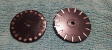
The hall sensor with reed switch magnet didn't pan out so well. Lost counts. Dish mover resync constantly. On the 'scope, one pole of the 6 sectors on the magnet showing a Significantly wider flux and one with a short one. Imagine the waveform.
My high res encoder wheel. Those miniature neodymium magnets from Amazon don't all have the same strength. Found that out the hard way.
And the ones that are equally strong have a flux that overlapped even on the biggest wheel I could fit in the gearbox. 43mm.
The smaller one was a total disaster. Mu-metal. Scrap old transformers, hard drives. Make a shield. Try another one. No go.
The weak ones. Used a magnetic compass and tried a stack of magnets to find enough that would deflect it at a measured distance from it equally.

Wait. Thinking. My machines used optical sensors to track high speed production. A guy in another city replaced a string of Honeywell cube emitter and detector sensor pairs. The the durned machine ran erratically. The supplier sent regular photodiode receivers instead of the correct Schmitt trigger ones. Analogy would be watching the sun go down as opposed to a camera shutter sequencing in front of your eyes. We aced it!

My Hall/magnet sensor "trip" was hindered by many things. If a trigger wheel could be made with a few magnets as opposed to the high res. one I really wanted. With a max. of the 43mm that would fit inside of the gearcase. It would work.
Optical don't care (like my relaxed, country, American English?). And the modification is safe. There is no hacking and soldering in the guts of the mover needed. And it's documented. I'd like to know why you're told to simply solder a wire from here to there, cut a trace or three. And there you have it.

Imagine designing and building a circuit for a potentiometer input only dish mover. There are a ton on eBay.
How would you do that?
Detect pulses. Count and retain them in memory.
Up and down.
Convert them to a/d. Convert that to a resistance that can be read by the mover.
And don't forget. Retain it all if power is removed.
Then figure out how to fit a multi-turn pot into a gearcase with reduction gearing. I'll pass.

My West and East limit is set by the switches. The mover is set to software limit at about -450. The other being + 4700. And 127W is my "home" sat at 0000 for resync. So from 131W-40.5W the counter goes to around 4500. Not too shab.
Enough to make you 'dangerous' now?
 

Attachments

  • Magnet Wheels.jpg
    Magnet Wheels.jpg
    241.8 KB · Views: 14

dreambox1959

Specialist Contributor
Joined
Feb 7, 2009
Messages
444
Reaction score
629
Points
93
Age
65
Location
46.3N-4.3E-FRANCE
My Satellite Setup
Octagon SF8008 - technomate 7100
My Location
france
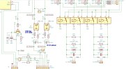
here is a part of my positioner design .
you can see the output protections and the pulse treatements
 

Attachments

  • command.jpg
    command.jpg
    216.9 KB · Views: 15

ArloG

Member
Joined
May 18, 2023
Messages
64
Reaction score
43
Points
18
Age
54
My Satellite Setup
12' Fiberglass Dish, C2W & Geosat Pro lnbf, Titanium ASC-1, Osmio4k, Zgemma H7 Client
My Location
N. Central PA, USA
here is a part of my positioner design .
you can see the output protections and the pulse treatements
Completely amazed at the forethought of your design. Not only TVS but varistors too.
I did a similar TVS protection on the ASC1. Tacked them to the traces and used adhesive pad strips to ground. Solder masked them in.
I was so giddy when the "LNB IS Short" message went away and my benched gearbox ran, that I put it back together and bolted the case shut.
Didn't even snap photos.
I have a few more to work on. One displays a motor short message. Another with a dead mcu and comparitors. No schematic.
So pulling diodes to check it they are Zener, Schottky and getting the values or if they are done. A bit of schematic scribbling. You know.
Not asking for great details here because that could get lengthy. Did you have a board populating service do the work?
Have you really made your very last one? Besides Brian, have you tried marketing them to others such as satellitedish.com or Ricks Satellite?
How many have you built and sold and are failure rates/warranty claims common? Found, and addressed?
If you were to ponder the attachment. What are chances a transcoder could be coded for an Arduino style of interface with multi line display?

Not every command would need to be implemented. Go-to, polarity, error detection. If entries needed to be added in the config file for satellite names the end user could edit. Page 79 would be where I went. Then navigate around to the various sections.
These commercial dish controls are readily available if you look on places like eBay. From azimuth only to az/el capable.
I have contacted the manufacturer. And a few of the still active software vendors. Nobody supports the DISEqC protocol.
So folks who buy them are usually getting up and pressing the buttons on them the move their dishes.
I have an Arduino library set for a stand alone dish mover using DISEqC commands form a receiver.
 

Attachments

  • RC1500A1.pdf
    2 MB · Views: 8

dreambox1959

Specialist Contributor
Joined
Feb 7, 2009
Messages
444
Reaction score
629
Points
93
Age
65
Location
46.3N-4.3E-FRANCE
My Satellite Setup
Octagon SF8008 - technomate 7100
My Location
france
I didn't understand all your questions, sorry!!!
I spoke with BRIAN about titanium but not to offer him my assembly.
I have made a small number of positioners for 4 years, I have made them evolve: switching power supply, cleaner internal wiring etc....
Last month I built 3 for our Italian colleagues.
I am not interested in selling on a larger scale.
I am addressing enthusiasts like us.
I could create a diseqc to serial interface for you to control an RC2000 if you get one.
 
Top