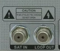
I now have a third receiver Octagon SF8008 connected via this method using DiSEqC 1.0 switch in reverse and again I can confirm it works a treat!

I looked into this, again.
I can now imagine that it can work, because of the
collector and emitter of the switching transistor
being interchanged; as in contrast with the setup for the transistor in a normal current flow.
But I'm not a electronics specialist at all, I must confess; so this is just all an assumption by me now.
I guess this can only work when there is a resistor between base and emitter(new collector), so that a small switching voltage/current can flow between base and collector(new emitter), that starts the 'emitter-collector current'. A resistor, such as in schematics as this: http://juras-projects.net/images/diseqccirc2.png
(e.g. R5, 10k, for transistor VT6-1)
So I guess it might not work when the switch has NO such resistor added, such as in schematics like this:
Misc Info - Juraś-Projects
(no resistor at switching transistor e.g. VT6)
However,
the transistors are not made for this use. I'm not sure if they will always survive (even with motor current?).

In fact, after reading some topics on the internet about this collector/emitter swapping: it might be that normal diseqc switch operation might be problematic, after this use.
And when you've one receiver on 13V, and another at 18V, there is no protection for the receivers to prevent possible damage.

That is why I wouldn't prefer to use this method, frankly. In cases like this, I'd rather take an old splitter, 'empty' it from its contents, and put some diodes in it (and maybe some capacitors). That would do the same job, WITH the voltage protection.
But, it is special to know that it works! Maybe some people would like to use this method.

greetz,
A33


