Ajak Patriot

ArloG

Member
Joined
May 18, 2023
Messages
64
Reaction score
42
Points
18
Age
54
My Satellite Setup
12' Fiberglass Dish, C2W & Geosat Pro lnbf, Titanium ASC-1, Osmio4k, Zgemma H7 Client
My Location
N. Central PA, USA
Just an FYI but might work for you okay.
I found using small 3mm neodymium bar and disc magnets on a high res wheel that fit inside the guts of a supercrap actuator.
The flux overlapped and caused inconsistent triggering. I tried making a shield for the hall sensor from hard drive mu metal.
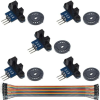
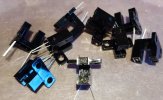
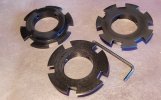
Nothing worked very well. In the attachment are the optical sensors I tried. But made my own trigger wheel.
They are really quite small and have an indicator led onboard. Got them from Amazon.
Of course your actuator control needs to have provision for 3 terminal devices or do as I did.
 

Attachments

  • Screenshot 2024-07-22 at 00-33-17 DAOKI 5Pcs Speed Measuring Sensor IR Infrared Slotted Optica...png
    Screenshot 2024-07-22 at 00-33-17 DAOKI 5Pcs Speed Measuring Sensor IR Infrared Slotted Optica...png
    211.7 KB · Views: 86

RimaNTSS

Super Moderator
Staff member
Joined
Jan 7, 2009
Messages
5,687
Reaction score
6,186
Points
113
Age
59
My Satellite Setup
Some SAT-related hardware.
My Location
N-E from Riga
While waiting for small magnets to arrive from PRC, found at home some 5x3mm neodymium magnets. They are a little bit too strong for my needs, however they also work, but the reed switch should be placed faraway. Made 3 wheels with 5, 6 and 7 magnets. By now, I feel that 6 magnets are the best solution, as this wheel gives 600 counts when the mount turns from end to end position. IMG_20240725_213935.jpgIMG_20240725_215002.jpg
 

ArloG

Member
Joined
May 18, 2023
Messages
64
Reaction score
42
Points
18
Age
54
My Satellite Setup
12' Fiberglass Dish, C2W & Geosat Pro lnbf, Titanium ASC-1, Osmio4k, Zgemma H7 Client
My Location
N. Central PA, USA
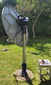
Just a little show and tell. Here's my setup. And yes. Neodymiums are strong enough to extend the pulse width of the switch action.
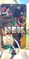
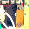
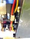
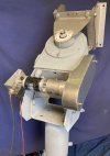
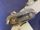
A few pics show the optical encoder I made and installed in my actuator.
The full view of the gearbox shows the braking relay top left.
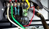
And there' s the SSR hooked up to my ASC-1 dish mover. Normally uses a reed switch but easily adapted for hall/optical.
Inside of the tape is a wave shaping network consisting of a capacitor, resistor, and Schottky diode.
 

Attachments

  • ASC1_SSR.jpg
    ASC1_SSR.jpg
    682.6 KB · Views: 35
  • Gearbox_Optical.jpg
    Gearbox_Optical.jpg
    1.2 MB · Views: 35
  • Optical_Cropped.jpg
    Optical_Cropped.jpg
    276.8 KB · Views: 33
  • Optical_Side.jpg
    Optical_Side.jpg
    801.5 KB · Views: 44

RimaNTSS

Super Moderator
Staff member
Joined
Jan 7, 2009
Messages
5,687
Reaction score
6,186
Points
113
Age
59
My Satellite Setup
Some SAT-related hardware.
My Location
N-E from Riga
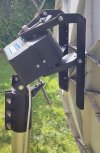
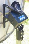
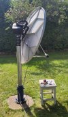
That is a pity, Channel Master did not make 1.5m antenna :angry:. If they were, Ajak Patriot would easily handle it. 1.2m antenna is a piece of cake for Patriot. So, installed CM 1.2 and it works just great. Dish goes H-H in just 70 seconds. In the end positions, antenna does not touch the pole.
 

Attachments

  • IMG_20240806_125231.jpg
    IMG_20240806_125231.jpg
    418.7 KB · Views: 43
  • IMG_20240806_122750.jpg
    IMG_20240806_122750.jpg
    398.7 KB · Views: 35
  • IMG_20240806_121108.jpg
    IMG_20240806_121108.jpg
    1 MB · Views: 34
  • IMG_20240806_120911.jpg
    IMG_20240806_120911.jpg
    1.1 MB · Views: 40

Captain Jack

Retired human
Joined
Oct 21, 2006
Messages
11,919
Reaction score
8,086
Points
113
My Satellite Setup
See signature
My Location
North Somerset
That is a pity, Channel Master did not make 1.5m antenna :angry:. If they were, Ajak Patriot would easily handle it. 1.2m antenna is a piece of cake for Patriot. So, installed CM 1.2 and it works just great. Dish goes H-H in just 70 seconds. In the end positions, antenna does not touch the pole.
Would this handle a 1.8m CM or is that a little too much?
 

RimaNTSS

Super Moderator
Staff member
Joined
Jan 7, 2009
Messages
5,687
Reaction score
6,186
Points
113
Age
59
My Satellite Setup
Some SAT-related hardware.
My Location
N-E from Riga

Trust

Specialist Contributor
Joined
Jul 18, 2004
Messages
1,139
Reaction score
1,623
Points
113
Age
78
My Satellite Setup
1.8 m CM at SMR 1224 + Elev. with 7 lnb changer Ku (lin - circ) - Ka (lin - circ) C (lin - circ)
My Location
Nijmegen Netherlands

Attachments

  • back.jpg
    back.jpg
    991.1 KB · Views: 28
  • open chain detail.jpg
    open chain detail.jpg
    133.9 KB · Views: 43

ArloG

Member
Joined
May 18, 2023
Messages
64
Reaction score
42
Points
18
Age
54
My Satellite Setup
12' Fiberglass Dish, C2W & Geosat Pro lnbf, Titanium ASC-1, Osmio4k, Zgemma H7 Client
My Location
N. Central PA, USA
I immediately see a NEMA stepper upgrade. With or without gear reduction and direct shaft coupling.
 

RimaNTSS

Super Moderator
Staff member
Joined
Jan 7, 2009
Messages
5,687
Reaction score
6,186
Points
113
Age
59
My Satellite Setup
Some SAT-related hardware.
My Location
N-E from Riga
Made an attachment for the optical sensor with 5-slot disc. Optical_disc.jpg
 

ArloG

Member
Joined
May 18, 2023
Messages
64
Reaction score
42
Points
18
Age
54
My Satellite Setup
12' Fiberglass Dish, C2W & Geosat Pro lnbf, Titanium ASC-1, Osmio4k, Zgemma H7 Client
My Location
N. Central PA, USA
Good job. I'd like to ask. Are you using a photoemitter/detector module or a true Schmitt trigger output?
I only noticed because a true photoswitch would have only 3 terminals. I figure you already know it but still have to expand on it.
If it is in fact the first one. If the motor were to stop on "half exposed/half blocked" on the trigger wheel. You may have a signal in no-mans land on the output.
In other words. If you slowly block the beam and check the output with a multimeter. Voltage (or current) would proportionally change.
If you use a Schmitt trigger with an NPN sinking output. Blocking the beam would keep the meter reading steady until a threshold was reached.
And the reading would "snap" to close-to 0 ohms, or snap open circuit when unblocked.. Just like reed switch would.
It could be the other way around. But the function is still the same. Snap open, snap closed.
Just had to add that. Looks like it's coming along nicely.
 

RimaNTSS

Super Moderator
Staff member
Joined
Jan 7, 2009
Messages
5,687
Reaction score
6,186
Points
113
Age
59
My Satellite Setup
Some SAT-related hardware.
My Location
N-E from Riga
photoemitter/detector module or a true Schmitt trigger output?
TBH, I do not know much about them :( Just found several in my boxes and fitted it to Ajak. I hope to get additional info from you and other forum members (I think that forum is for).
So, in the beginning I decided to do the hardware and then think how to connect the optical module to the positioner. BTW, there is another disc I made with 6 slots, perhaps need another one with 7 slots. IMG_20240813_164215.jpg
 

ArloG

Member
Joined
May 18, 2023
Messages
64
Reaction score
42
Points
18
Age
54
My Satellite Setup
12' Fiberglass Dish, C2W & Geosat Pro lnbf, Titanium ASC-1, Osmio4k, Zgemma H7 Client
My Location
N. Central PA, USA
Is there part number on the sensor? If so I could look up the data sheet for it.
It's cool when you can retrofit things without a bunch of mods.
As far as slots go. That depends on where the encoder is mounted and how much resolution you will need.
Another thing to consider is if there is any motor coast when the actuator stops on a satellite.

I've found that you can actually have too many slots (or magnets in that case).
The optical sensor I use is tons better than the hall sensor.
I think my final encoder wheel has 12 slots. In regular satellite to satellite positioning it works perfect.
Mind you, I do use a linear actuator. And the encoder is fixed to the drive gear that couples to the actuator tube shaft.
12 "counts", 1 turn of the shaft. Right?

Even though the gear reduction is pretty high. When the motor shut off, the armature would coast down to a stop. Pretty fast. But still.
When blindscanning and initially finding all of the sats. in the arc. Searching for signals and interpolating where one should be from simple math.
"Bumping" the dish mover E & W to find and peak signal. Errors would add up.
What I see. And maybe the vboxes are different. When the motor is shut off, so is the counter.
So. If the trigger wheel is on the verge of either covering or uncovering the sensor. Just that little bit of residual coast would tell the mover that the gears have moved "that much more" Make sense?
But since it has triggered after the counter shut off. It missed it and the next time it's turned on, waits one pulse. It adds up.
Especially when you bump the dish.
So when setting up satellites. Every few times I go back to the home, 0000, satellite. Peak signal. And resync from the menu.
Maybe after storing a few sats. You go back to your home satellite and find that signal is peaked at -0012. Resync there and it then is indexed at 0000 again. And the rest of your previously stored satellites with be on target. Exception being the very last one. Which moving +12 counts should peak the signal. Store it there in the memory slot.

Less encoder slots, more "dead man land". More can lead to the above. My 12' dish really sings with the new setup. Probably 10 counts either way and signal drops drastically. I'm positive ku band would probable be more lenient.

One cheat I did was to put an automorive headlamp bulb in parallel with a toggle switch. And then put the switch in series with the motor leads.
So when the switch was closed, the motor ran regular speed. Opening the switch put the bulb in circuit and jogging the motor slower made for accurate signal peaking. And of course there is the dynamic brake, above, that stops the armature almost immediately.
It's a rant. But more info. than anyone else can give. I love this stuff!
 

RimaNTSS

Super Moderator
Staff member
Joined
Jan 7, 2009
Messages
5,687
Reaction score
6,186
Points
113
Age
59
My Satellite Setup
Some SAT-related hardware.
My Location
N-E from Riga
My optical switches are marked HY on one side and diode sign on another side, and H505 in the middle. But, if those are not proper ones, I can buy another ones. Also made wheel with 7 slots. I just wonder what kind of adapter do I need to use between the optical sensor and the positioner to make it generate pulses as the reed switch does. Will deal with errors afterward.
 

Attachments

  • IMG_20240813_184851.jpg
    IMG_20240813_184851.jpg
    390.8 KB · Views: 14
  • IMG_20240813_181929.jpg
    IMG_20240813_181929.jpg
    305.5 KB · Views: 17

Beli1910

Member
Joined
Mar 12, 2023
Messages
254
Reaction score
221
Points
43
Age
45
Location
Sevnica-Slovenija
My Satellite Setup
Gibertini 150 with diqec motor 90E -30W
Wave frontier t90 45E-5W
Triax 110-,motor
Laminas 1.8m and Laminas 120
Chanel master 125
Gibertini 150 fix
Gibertini 125
Etc....
My Location
Sevnica 8290-Slovenija
Rima, can you tell me what noise the motor makes when it rotates the antenna?
 

RimaNTSS

Super Moderator
Staff member
Joined
Jan 7, 2009
Messages
5,687
Reaction score
6,186
Points
113
Age
59
My Satellite Setup
Some SAT-related hardware.
My Location
N-E from Riga

ArloG

Member
Joined
May 18, 2023
Messages
64
Reaction score
42
Points
18
Age
54
My Satellite Setup
12' Fiberglass Dish, C2W & Geosat Pro lnbf, Titanium ASC-1, Osmio4k, Zgemma H7 Client
My Location
N. Central PA, USA
My optical switches are marked HY on one side and diode sign on another side, and H505 in the middle. But, if those are not proper ones, I can buy another ones. Also made wheel with 7 slots. I just wonder what kind of adapter do I need to use between the optical sensor and the positioner to make it generate pulses as the reed switch does. Will deal with errors afterward.
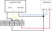
Look at the interface I made for my ASC1. A Crydom solid state relay. 3-32 VDC in and the output can handle up to 10 VDC.
Complete a circuit on the input side with the photodiode of your sensor in series with a power source adequate for the diode to conduct and in its voltage range. At least 3 VDC. The output connects to your sensor input. Measure the polarity of the vbox sensor terminals. Hook the SSR output terminals correctly.
When the photodiode sees the emitter in the u-shaped through beam sensor, it should conduct.
It completes the SSR input and the output conducts. As the reed switch would do.

You don't need a Crydom SSR. Any one with DC in/output and of a lower voltage spec. will do.
There are tons on eBay.
 

Attachments

  • ASC1 Hall SSR.jpg
    ASC1 Hall SSR.jpg
    716.8 KB · Views: 13

Trust

Specialist Contributor
Joined
Jul 18, 2004
Messages
1,139
Reaction score
1,623
Points
113
Age
78
My Satellite Setup
1.8 m CM at SMR 1224 + Elev. with 7 lnb changer Ku (lin - circ) - Ka (lin - circ) C (lin - circ)
My Location
Nijmegen Netherlands
I immediately see a NEMA stepper upgrade. With or without gear reduction and direct shaft coupling.
there is no room for direct coupling , you will lose a part of west arc .
beside , this 30 v DC motor can be controlled with every regular positioner .
 

RimaNTSS

Super Moderator
Staff member
Joined
Jan 7, 2009
Messages
5,687
Reaction score
6,186
Points
113
Age
59
My Satellite Setup
Some SAT-related hardware.
My Location
N-E from Riga
I've ordered several such optical converters with circuit boards. Will continue project when they arrive. ScreenHunter 448.jpg
 

RimaNTSS

Super Moderator
Staff member
Joined
Jan 7, 2009
Messages
5,687
Reaction score
6,186
Points
113
Age
59
My Satellite Setup
Some SAT-related hardware.
My Location
N-E from Riga
OK, optical converters arrived another day. Another mounting was needed, but that is done. I was hoping, the converter makes pulses like the reed switch does, but they only give +5V when there is a slot in the wheel. Basically, as @ArloG is saying, I will need to install additional SSR or, maybe, a mechanical 5V relay. IMG_20240830_190533.jpg
 

Trust

Specialist Contributor
Joined
Jul 18, 2004
Messages
1,139
Reaction score
1,623
Points
113
Age
78
My Satellite Setup
1.8 m CM at SMR 1224 + Elev. with 7 lnb changer Ku (lin - circ) - Ka (lin - circ) C (lin - circ)
My Location
Nijmegen Netherlands
the output will be zero when the opto is blocked by the wheel , it will work , mine works the same way .
What positioner do you use ?
 
Top