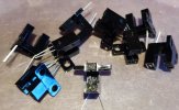
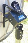
Is there part number on the sensor? If so I could look up the data sheet for it.
It's cool when you can retrofit things without a bunch of mods.
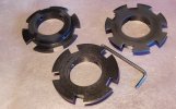
As far as slots go. That depends on where the encoder is mounted and how much resolution you will need.
Another thing to consider is if there is any motor coast when the actuator stops on a satellite.
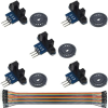
I've found that you can actually have too many slots (or magnets in that case).
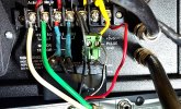
The optical sensor I use is tons better than the hall sensor.
I think my final encoder wheel has 12 slots. In regular satellite to satellite positioning it works perfect.
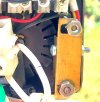
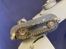
Mind you, I do use a linear actuator. And the encoder is fixed to the drive gear that couples to the actuator tube shaft.
12 "counts", 1 turn of the shaft. Right?
Even though the gear reduction is pretty high. When the motor shut off, the armature would coast down to a stop. Pretty fast. But still.
When blindscanning and initially finding all of the sats. in the arc. Searching for signals and interpolating where one should be from simple math.
"Bumping" the dish mover E & W to find and peak signal. Errors would add up.
What I see. And maybe the vboxes are different. When the motor is shut off, so is the counter.
So. If the trigger wheel is on the verge of either covering or uncovering the sensor. Just that little bit of residual coast would tell the mover that the gears have moved "that much more" Make sense?
But since it has triggered after the counter shut off. It missed it and the next time it's turned on, waits one pulse. It adds up.
Especially when you bump the dish.
So when setting up satellites. Every few times I go back to the home, 0000, satellite. Peak signal. And resync from the menu.
Maybe after storing a few sats. You go back to your home satellite and find that signal is peaked at -0012. Resync there and it then is indexed at 0000 again. And the rest of your previously stored satellites with be on target. Exception being the very last one. Which moving +12 counts should peak the signal. Store it there in the memory slot.
Less encoder slots, more "dead man land". More can lead to the above. My 12' dish really sings with the new setup. Probably 10 counts either way and signal drops drastically. I'm positive ku band would probable be more lenient.
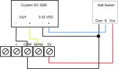
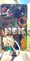
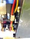
One cheat I did was to put an automorive headlamp bulb in parallel with a toggle switch. And then put the switch in series with the motor leads.
So when the switch was closed, the motor ran regular speed. Opening the switch put the bulb in circuit and jogging the motor slower made for accurate signal peaking. And of course there is the dynamic brake, above, that stops the armature almost immediately.
It's a rant. But more info. than anyone else can give. I love this stuff!


 . If they were, Ajak Patriot would easily handle it. 1.2m antenna is a piece of cake for Patriot. So, installed CM 1.2 and it works just great. Dish goes H-H in just 70 seconds. In the end positions, antenna does not touch the pole.
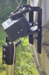
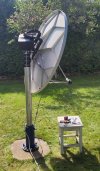
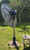
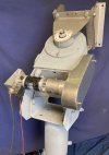

 Just found several in my boxes and fitted it to Ajak. I hope to get additional info from you and other forum members (I think that forum is for).