Just Sharing This My Channel Master 1.8 project.

Manikm909

Small'ish Dish Man
Joined
Sep 10, 2020
Messages
2,476
Reaction score
1,168
Points
113
Age
48
My Satellite Setup
Channel Master 1.8M on Edision MIO 4K & GTMEDIA Combo, and CM1.2M on Octagon SF8008
My Location
Kent, UK
i'll be fitting Rimants arms this weekend, and fitting the CBAND LNB for my first dip in the CBAND experience.
 

moonbase

Small Dish Man
Joined
Mar 29, 2004
Messages
4,525
Reaction score
4,657
Points
113
My Satellite Setup
.
My Location
UK
thanks @moonbase

its not that complicated - the issue is far more simple than that ....


its putting me off going out WEST - to play with CBAND at the moment


If the issue is simple then you should be able to fix it quickly and easily, good luck...
 

Manikm909

Small'ish Dish Man
Joined
Sep 10, 2020
Messages
2,476
Reaction score
1,168
Points
113
Age
48
My Satellite Setup
Channel Master 1.8M on Edision MIO 4K & GTMEDIA Combo, and CM1.2M on Octagon SF8008
My Location
Kent, UK
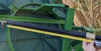
how many more inches do i have left to go further west ...this is a 24" jack - gone from 54e to its position as photographed at 45w...its used 19 inches
do you think i can reach 58w ? or will the end of the arm fall out and cause a big kerfuffle.

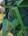
also to remove this plate or not? and go with either yellow or blue position?
 

Attachments

  • PXL_20220325_134321236.jpg
    PXL_20220325_134321236.jpg
    333.8 KB · Views: 63
  • PXL_20220325_134826539.jpg
    PXL_20220325_134826539.jpg
    373.4 KB · Views: 50

moonbase

Small Dish Man
Joined
Mar 29, 2004
Messages
4,525
Reaction score
4,657
Points
113
My Satellite Setup
.
My Location
UK
how many more inches do i have left to go further west ...this is a 24" jack - gone from 54e to its position as photographed at 45w...its used 19 inches
do you think i can reach 58w ? or will the end of the arm fall out and cause a big kerfuffle.


You should be OK for another four inches.
You might need to adjust the black flywheel cam that limits West extension if it stops before you get a full extension.

Whether or not another four inches will get you from 45W to 58W depends on the geometry of the polar mount planar triangle.

Just fit the 36" one, end of story...
There is plenty out West in C-Band for Poop slurpers.
 

RimaNTSS

Super Moderator
Staff member
Joined
Jan 7, 2009
Messages
5,684
Reaction score
6,180
Points
113
Age
59
My Satellite Setup
Some SAT-related hardware.
My Location
N-E from Riga
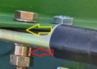
@Manikm909 I wonder what you have where yellow arrow is pointed? Perhaps there should be a spacer like that pointed by the red arrow.
 

Attachments

  • PXL_20220325_134321236.jpg
    PXL_20220325_134321236.jpg
    59.8 KB · Views: 58

a33

Specialised Contributor
Joined
Sep 24, 2009
Messages
1,327
Reaction score
755
Points
113
Age
64
My Satellite Setup
XSAT410
Rebox RE-9000
My Location
The Netherlands
also to remove this plate or not? and go with either yellow or blue position?

That could be dependent on which is the most easterly satellite (max. retracted) that you want to receive, and which is the most westerly satellite (max. extended)?

And blue or yellow position: maybe dependent on the triangle side lengths that you want?

Greetz,
A33
 

Channel Hopper

Suffering fools, so you don't have to.
Staff member
Joined
Jan 1, 2000
Messages
36,009
Reaction score
8,720
Points
113
Age
60
Website
www.sat-elite.uk
My Satellite Setup
A little less analogue, and a lot more crap.
My Location
UK
how many more inches do i have left to go further west ...this is a 24" jack - gone from 54e to its position as photographed at 45w...its used 19 inches
do you think i can reach 58w ? or will the end of the arm fall out and cause a big kerfuffle.

also to remove this plate or not? and go with either yellow or blue position?
 

Manikm909

Small'ish Dish Man
Joined
Sep 10, 2020
Messages
2,476
Reaction score
1,168
Points
113
Age
48
My Satellite Setup
Channel Master 1.8M on Edision MIO 4K & GTMEDIA Combo, and CM1.2M on Octagon SF8008
My Location
Kent, UK
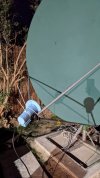
i found a very robust CBAND LNB holder up the garage tonight.
:)
 

Attachments

  • PXL_20220325_192452651.MP.jpg
    PXL_20220325_192452651.MP.jpg
    343.9 KB · Views: 57

moonbase

Small Dish Man
Joined
Mar 29, 2004
Messages
4,525
Reaction score
4,657
Points
113
My Satellite Setup
.
My Location
UK
i found a very robust CBAND LNB holder up the garage tonight.
:)


You got the wrong type of scalar on the LNBF, should be hooded for offset focus dish.
Signals should still be decent though, perhaps a dB down or slightly more.

You slurping Poop yet, that 55.5W is like a bisto factory?
 

Manikm909

Small'ish Dish Man
Joined
Sep 10, 2020
Messages
2,476
Reaction score
1,168
Points
113
Age
48
My Satellite Setup
Channel Master 1.8M on Edision MIO 4K & GTMEDIA Combo, and CM1.2M on Octagon SF8008
My Location
Kent, UK
omg your right!!! i fitted the prime focus style one, oh well, job for the morning - thought something didnt look right!

no, i cant get to 55w - ERR2 - i will fit the 36" in the morning - @Channel Hopper will be very pleased.
 

jeallen01

Specialist Contributor
Joined
Oct 12, 2003
Messages
6,674
Reaction score
2,630
Points
113
My Satellite Setup
See Signature
My Location
Somewhere in England (possibly?)!
What sort of cable are you using for the pulse circuit? I use a seperate cable that is screened for the pulse circuit, I dont have any problem. Its possible that your pulses are being corrupted by interference from the motor cable. As Moonbase says really an RC2000 is the way to go..
That's the reason why, elsewhere in this or another thread, I commented that "old style" multicore cable for H-H mounts or actuators was generally screened - but, to be more precise, the 2 cores for the sensing circuit were screened together, whereas the +/- 36V motor/actuator cores were not, and the sensor circuit screening was usually grounded to the Rx chassis at one end and to the motor/actuator casing at the other to create an "end-to-end" screened circuit.

BTW: I still have a few metres of that type of cable in the garage from when I took the Jaeger H-H mount down a few years ago.
 

7mdish

Regular Member
Joined
Aug 11, 2013
Messages
666
Reaction score
271
Points
63
My Satellite Setup
CM 2.4m motorised offset dish, Viking Ku-band 2-ports motorised feed, 2 SMW LNBs, RC2000A, Dreambox DM920.
My Location
Milan, Italy
In the RC2000's user manual, Research Concept suggests to connect the ground wire only to the controller pin but not to the motor ground. It must be leaved opened at the motor side. So, only one cap of the cable must be connected. Doing this, the cable is shielded but possible ground loops are avoided.
 

jeallen01

Specialist Contributor
Joined
Oct 12, 2003
Messages
6,674
Reaction score
2,630
Points
113
My Satellite Setup
See Signature
My Location
Somewhere in England (possibly?)!
In the RC2000's user manual, Research Concept suggests to connect the ground wire only to the controller pin but not to the motor ground. It must be leaved opened at the motor side. So, only one cap of the cable must be connected. Doing this, the cable is shielded but possible ground loops are avoided.
OH DEAR, OH DEAR, "the old, old wives' tale" of leaving one end of the shield of a shielded cable unconnected to avoid ground loops!!!!:rolleyes:

Having worked for quite a long time in the industrial and defence sectors in EMC control (as well as electrical/electronic safety control!), I can tell you that doing this this is VERY much depricated because it leaves the sensing circuits in the motor/actuator "floating" and likely to pick up/radiate any interference that's around - including that on the motor cable cores!

As an example of something very similar, in my last job, I was given a long sensor probe to get EMC certified (for CE Marking purposes) but the first time I tested it in a screened the bloody thing spewed RF right across the spectrum and I had to abort the testing very quickly.

Investication uncovered that the cable was in 3 sections:
- 2 lengths of heavily screened cable, one of which connected to the probe
- a short intermediate section consisting of a plastic box and small circuit board, the ground connections to which were virtually non-existent, and absolutely no use for EM control because that also meant the probe cable screen and probe were effectively ungrounded for for EMC purposes.

Long story cut short: replaced the plastic box by a metal one with proper 360 deg metal cable glands at either end to ensure the circuit board was screened and that the screen was contiguous throughout the length of the probe cable, and also improved the continuity of the cable connections to the exterior control box and the probe.

Result: the modified probe sailed through the relevant industrial level RF emissions, immunity and surge tests pretty much first time. (and that did my status as a pretty new contractor absolutely no harm at all - I finally stayed there for nearly 3 yrs and fixed quite a few other EMC issues along the way :)!).

Thus, grounding the shield at BOTH the RX and motor/actuator ends ensures that any such interference doesn't get onto the sensing cores due to the "skin effect" phenomena which restricts it to the outer skin of the shield, and then to the chassis of the Rx and thus to the outer skin of a Faraday cage - thus the interference doesn't get into the internally located sensing circuits at either end.
 
Last edited:

7mdish

Regular Member
Joined
Aug 11, 2013
Messages
666
Reaction score
271
Points
63
My Satellite Setup
CM 2.4m motorised offset dish, Viking Ku-band 2-ports motorised feed, 2 SMW LNBs, RC2000A, Dreambox DM920.
My Location
Milan, Italy
Really thank you jeallen01 for your extensive explanation. Very clear.
So, as I must really install my new setup soon (hoping soon, I'm waiting for delivery of my new 2.4m dish), it seems that I must connect both side of the shield in motor cable.
My setup provides RC2000 controller with two actuators (for elevation correction, too), so a double motor cable must be used.
Please note that non-connection to the motor side is specified more than one time and in uppercase letters in the RC2000 user manual......
But your explanation seems totally reversing this choice.
Thank you again.
 

Channel Hopper

Suffering fools, so you don't have to.
Staff member
Joined
Jan 1, 2000
Messages
36,009
Reaction score
8,720
Points
113
Age
60
Website
www.sat-elite.uk
My Satellite Setup
A little less analogue, and a lot more crap.
My Location
UK
how many more inches do i have left to go further west ...this is a 24" jack - gone from 54e to its position as photographed at 45w...its used 19 inches
do you think i can reach 58w ? or will the end of the arm fall out and cause a big kerfuffle.

also to remove this plate or not? and go with either yellow or blue position?
Having looked at the first picture, if you are replacing the actuator for the recommended size to get to the far west, stick it on the other side of the polarmount since you will be further on the west side than east.
 

jeallen01

Specialist Contributor
Joined
Oct 12, 2003
Messages
6,674
Reaction score
2,630
Points
113
My Satellite Setup
See Signature
My Location
Somewhere in England (possibly?)!
Really thank you jeallen01 for your extensive explanation. Very clear.
So, as I must really install my new setup soon (hoping soon, I'm waiting for delivery of my new 2.4m dish), it seems that I must connect both side of the shield in motor cable.
My setup provides RC2000 controller with two actuators (for elevation correction, too), so a double motor cable must be used.
Please note that non-connection to the motor side is specified more than one time and in uppercase letters in the RC2000 user manual......
But your explanation seems totally reversing this choice.
Thank you again.
That sort of "advice" prompts the thought that the controller manufacturer didn't have a very good grasp of good EMC design and construction methodologies and knew that the unit has a somewhat "fragile" EMC performance, but didn't know how-to/want-to-try to fix it, and thus wanted to hand over responsibilty any EMC-related problems to the installer/end-customer!:rolleyes:
 
Top